0
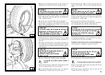
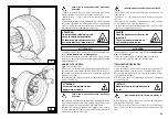
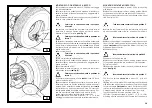
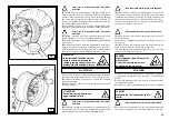
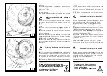
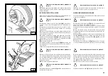
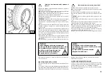
5)
Sollevare il cerchio con il pneumatico agganciato e ruotarlo
in senso antiorario di 15-20 cm. Il pneumatico si posizionerà in
modo obliquo rispetto al cerchio.
6)
Portare il braccio portautensili in posizione di fuori lavoro;
traslarlo sul fianco interno del pneumatico e riagganciarlo in
questa posizione.
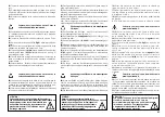
7)
Verificare che l'utensile a becco sia posizionato sul lato della
ruota. In caso contrario ruotare di 180°.
5)
Lift the rim with the tyre hook to it and turn it anticlockwise
about 15-20 cm. The tyre will be positioned tilted across the
rim.
6)
Move the tool carrier arm to its non-working position. Move it
to the inside plane of the tyre and rehook it in this position.
7)
Check to make sure the hook tool is positioned on the wheel
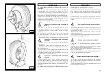
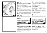
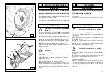
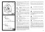
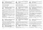
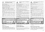
Portarsi con la colonnetta mobile in posizione
di lavoro D.
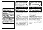
8)
Avanzare con l'utensile fino a portare il suo punto rosso di
riferimento in asse con il bordo esterno del cerchio ad una
distanza di 5 mm. dallo stesso
(vedi Fig. S).
8)
Move the tool forward until the red reference dot is lined
up with the outside edge of the rim and about 5 mm from it
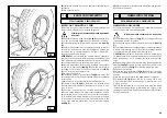
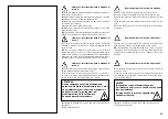
9)
Portandosi sull'esterno della ruota controllare visivamente
l'esatta posizione dell'utensile ed eventualmente correggerla,
quindi ruotare l'autocentrante in senso
orario
fino a portare
la pinza nel punto più in basso (ore 6). Il primo tallone risulterà
inserito nel cerchio.
Rimuovere la pinza.
9)
Move to the outside of the wheel and check the exact posi-
tion of the hook visually and adjust it as needed. Then turn the
spindle
clockwise
until the clip is at the bottom (6 o’clock). The
first bead will be on the rim.
Remove the clip.
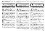
Portarsi con la colonnetta mobile in posizione di
lavoro C.
10)
Fare uscire l'utensile dal pneumatico.
11)
Portare il braccio portautensili in posizione di fuori lavoro;
traslarlo sul fianco esterno del pneumatico.
12)
Ruotare l'utensile di 180°
Portarsi con la colonnetta mobile in posizione
di lavoro D.
Take the mobile control unit to work position D.
10)
Remove the tool from the tyre.
11)
Move the tool carrier arm to its non-working position. Move
it to the outside plane of the tyre.
12)
Turn the tool 180°
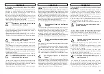
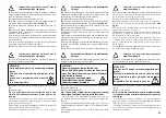
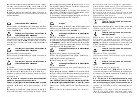
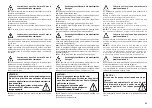
13)
Ruotare l'autocentrante fino a portare il foro della valvola
in basso (a ore 6).
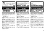
14)
Portare la pedana mobile
(4, Fig. A)
sulla verticale della
ruota ed abbassare l'autocentrante fino ad appoggiare l'au
-
tocentrante sulla pedana stessa.
Traslare la pedana verso l'esterno in modo da creare uno spa-
zio, tra pneumatico e cerchio, nel quale introdurre la camera
d'aria.
N.B.: Il foro per la valvola può trovarsi in posizione asimmetrica
rispetto al centro del cerchio.
In questo caso è necessario posi-
zionare ed introdurre la camera d'aria come indicato in fig. T.
Introdurre la valvola nel foro e fissarla mediante la sua ghiera.
15)
Introdurre la camera d'aria nel canale del cerchio (N.B.:
per agevolare l'operazione è consigliabile ruotare contempo-
raneamente l'autocentrante in senso orario).
13)
Turn the spindle until the valve hole is at the bottom (6
o’clock).
14)
Move the platform
(4 Fig. A)
under the wheel and lower
the spindle until the tyre is pressed down against the platform
. As the platform is moved slightly towards the outside, the tyre
will open a little and thus create enough space to insert the
inner tube.
NB: The valve hole may be asymmetrical to the centre of the
rim. In this case position and insert the inner tube as shown in
Fig. T.
Insert the valve through the hole and fix it with its locking ring.
T
Portarsi con la colonnetta mobile in posizione
di lavoro B.
Take the mobile control unit to work position D.
Take the mobile control unit to work position C.
Take the mobile control unit to work position B.
S


