15
Mise en place de la machine
Mode d’emploi - geodyna 990-2,990mot,992 - ZEEWB724B03
Installation of the machine
Operation manual - geodyna 990-2,990mot,992 - ZEEWB724B03
2.3
Montage du carter de roue et
du porte–carter.
(fourni en option sur geodyna 990-2 et 992)
Le porte–carter est monté sur la face arrière de la
machine, tandis que le carter lui–même est monté sur
le côté droit.
y
Arrêter la machine en appuyant sur l’interrupteur
principal.
y
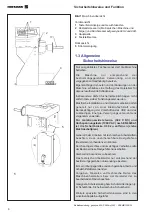
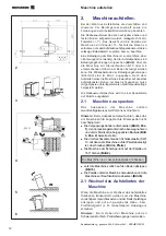
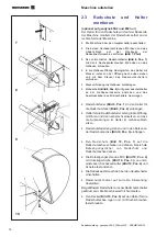
Desserrer les deux vis à tête hexagonale M5 et
enlever
le couvercle sur la face arrière de l’équilibreuse
(Fig.
7, flèche)
.
y
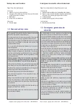
Fixer le porte-carter prémonté
(Fig. 8, pos. 1)
à
l’extérieur du bâti à l’aide des 4 vis à tête hexagonale
M8.
y
Insérer la main dans la découpe du bâti, sortir le
câble
avec fiche situé à droite de ladite découpe et le relier
à la prise de l’interrupteur du carter de roue.
y
Remettre la fiche à intérieur du bâti.
y
Coller le collier de serrage adhésif
(Fig. 8, pos. 2)
sur la face arrière du bâti, et ce en position centrée
face au porte–carter ; y déposer le câble
d’alimentation du micro–interrupteur.
y
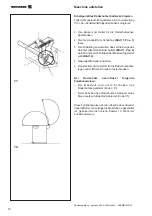
Accrocher le ressort du carter de roue
(Fig. 9, pos.
1)
au porte–ressort dudit ressort
(Fig. 9, pos. 2)
.
y
Insérer le porte–ressort du carter en biais dans la
découpe, le positionner ensuite verticalement, de
manière à ce que les évidements dudit porte–ressort
se trouvent à l’intérieur du panneau du bâti.
y
Tirer le ressort du carter pour le déployer et
l’accrocher au boulon de l’arbre dudit carter
(Fig. 9,
pos. 3)
.
y
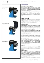
Enficher le carter de roue
(Fig. 10, pos. 1)
sur l’arbre
dudit carter et tourner jusqu’à ce que les trous de
fixation du carter de roue et de l’arbre dudit carter
coïncident.
y
Enficher la vis de fixation M10
(Fig. 10, pos. 2)
et la
rondelle
(Fig. 10, pos. 3)
de bas en haut, bien serrer
l’écrou hexagonal
(Fig. 10, pos. 4)
et la rondelle.
y
Mettre en marche l’équilibreuse en appuyant sur
l’interrupteur principal.
y
Contrôler le bon réglage de l’interrupteur du carter
de roue :
Ledit carter étant ouvert, l’interrupteur doit être appuyé.
La machine ne doit pas démarrer.
y
Poser le couvercle
(Fig. 10, pos. 5)
sur le porte–
arbre du carter de roue et fixer au moyen de vis à
tôle.
2.3
Fit wheel guard and holder
(optional on geodyna990-2 &992 only)
The holder for the wheel guard is fitted on the rear of the
wheel balancer, the wheel guard itself is fitted on the
right of the balancer.
y
Switch off the balancer at the mains switch.
y
Undo the two M5 hexagon head screws and remove the
rear cover plate of the wheel balancer
(Fig. 7, arrow)
.
y
Fit the pre-assemmbled wheel guard holder
(Fig. 8, item
1)
to the outside of the cabinet using the 4 hexagon bolts
M8.
y
Reach into the opening in the cabinet, pull out the lead
with plug located to the right of the opening and connect
it with the plug of the wheel guard switch.
y
Replace the plug connector into the cabinet.
y
Stick the adhesive clip (Fig. 8, item 2) on the rear of the
cabinet in a central position relative to the wheel guard
holder and insert the connecting lead of the microswitch.
y
Fit the wheel guard spring
(Fig. 9, item 1)
into the
spring holder
(Fig. 9, item 2)
.
y
Pass the holder for the wheel guard spring through
the opening, tilting it in the process, and then fit it
vertically so that the recesses in the holder are located
in the cabinet panel.
y
Extend the wheel guard spring and fit it into the bolt
on the wheel guard arbor
(Fig. 9, item 3)
.
y
Slide the wheel guard
(Fig. 10, item 1)
on the arbor
and raise it until the fastening holes of wheel guard
and wheel guard arbor coincide.
y
Insert the M10 setscrew
(Fig. 10, item 2)
with washer
(Fig. 10, item 3)
from below, and tighten the hexagon
nut
(Fig. 10, item 4)
and washer.
y
Turn on the wheel balancer at the mains switch.
y
Check wheel guard switch for correct setting:
When the wheel guard is open the wheel guard switch
must be pressed. The balancer must not start.
y
Place the cover
(Fig. 10, item 5)
onto the holder for
the wheel guard arbor and fasten by means of tapping
screws.

