105
Manuel d’Utilisation
Instructions d’installation
Operator’s Manual
Installation Instructions
geodyna 980L
geodyna 980L
i. Conditions d’installation.
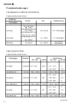
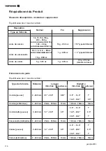
Conditions d’espace.
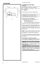
Les croquis indiquent les conditions minimum
nécessaires à la sécurité.
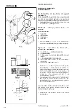
Voir les croquis pour les conditions d’espace:
i.1
geodyna 980L
Chaque croquis a deux séries de dimensions:
1 Lignes esquissées: pour les parts rapportées aux
trous de fixation au sol.
2 Lignes continues: pour parts rapportées à une
surface d'encombrement de la machine.
Conditions du sol.
Dans la région du support de la machine, le sol doit être
:
-
horizontal, tolérance
+/-1°.
-
plat; à 2 mm près
-
capable de supporter le poids de l’équilibreur indiqué
au Chapitre 2 du Manuel d’utilisation.
Le sol sur lequel l’équilibreur est installé ne doit pas
transmettre les vibrations d’autres appareils ou de
l’extérieur du bâtiment. Les vibrations externes
peuvent modifier la précision de l’unité.
Note
:
L’équilibreur doit être placé directement sur
le sol. N’utilisez pas d’anneaux pour combler les écarts.
Si les conditions ci-dessus sont respectées, il n’est
pas nécessaire de fixer l’équilibreur au sol.
Alimentation électrique.
Voir Chapitre 2 du Manuel d’utilisation pour les
principales conditions d’alimentation sur secteur.
ATTENTION
: VERIFIEZ QU’UNE PRISE MURALE DE
SECTEUR AGGREE EST DISPONIBLE.
ATTENTION
: NE GUIDEZ JAMAIS LES CABLES
D’ALIMENTATION SUR LE SOL, SAUF SI
PROTEGES PAR UNE COUVERTURE AGREEE.
i. Installation requirements.
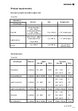
Space requirements.
The drawings show the minimum safety
requirements.
Refer to the drawings for space requirements:
i.1
geodyna 980L
Each drawing has two sets of dimensions:
1 dotted lines: for measurements regarding the holes
for fixing the machine to the floor
2 continuous lines: for measurements regarding overall
machine surface space
Floor requirements.
In the support area of the machine, the floor should be
:
-
horizontal;
+/-1° of tollerance.
-
even; within 2 mm
-
able to bear the weight of the balancer as stated in
Chapter 2 of the Operator’s Manual.
The floor on which the balancer will be installed
should not relay vibrations from other devices or from
outside the building. External vibrations may affect
the accuracy of the unit.
Note
:
The balancer must be positioned directly
on the floor. Do not use spacers to fill gaps.
If the above conditions are satisfied, the balancer
does not need fixing to the floor.
Power supply requirements.
Refer to Chapter 2 of the Operator’s Manual for mains
power requirements.
WARNING
: ENSURE THAT AN APPROVED WALL
MAINS OUTLET IS AVAILABLE.
WARNING
: NEVER GUIDE POWER SUPPLY
CABLES OVER THE FLOOR, UNLESS
PROTECTED BY AN APPROVED COVER.
Summary of Contents for EEWBUS732A
Page 102: ...102 geodyna 980L ...
Page 117: ...117 geodyna980L ...
Page 118: ...118 geodyna980L BLANK PAGE ...
Page 119: ...119 geodyna980L BLANK PAGE ...

