109
Manuel d’Utilisation
Instructions d’installation
Operator’s Manual
Installation Instructions
geodyna 980L
geodyna 980L
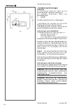
iii Procédures d’installation.
Unité:
Voir le graphique correct, section
i
, pour positionner
correctement l’équilibreur. Si l’équilibreur doit être
fixé, nous conseillons des éléments de fixation avec
un arbre d’écrou de 8 mm, qualité 8.8 ou supérieure.
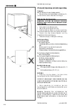
Crochets de stockage:
•
Déballez les 4 crochets et collerettes de stockage
filetés.
•
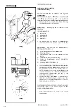
Voir Figure iii-1. Montez les 4 crochets et collerettes
filetés.
Moyen de la roue sur l’arbre principal
:
•
Avant de fixer le moyen de serrage de la roue,
nettoyer le cône de l’arbre principal
et le cône
intérieur du moyen de serrage.
Fig. iii-2 Montage du moyen de serrage
1
Cône de l’arbre principal
2
Corps de base du moyen de serrage
3
Vis de fixation (hexagone creux CH14)
4
Clé mâle (livré avec la machine)
•
Faire glisser le moyen de serrage sur le cône de
l’arbre principal de sorte que la tête de la vis à tête
cylindrique insérée au fond du cône s’engage dans
le corps de base.
•
Bien serrer le moyen de serrage à l’aide de la vis de
fixation.
Couvre roue :
•
Voir Figure iii-3. Vissez le couvre roue sur l’arbre qui
sort à l’arrière droit.
Appareils de serrage :
•
Ranger les éléments d'ancrage sur les pivots porte
accessoires et dans les logements préposés.
iii Installation procedures.
Wheel balancer:
Refer to the drawing in i for correct wheel balancer
positioning. If the wheel balancer needs securing, we
recommend fixing elements with a diameter of 8 mm,
quality 8.8 or higher.
Supports for Accessories:
•
Unpack the 4 threaded accessory support studs and
the support plates.
•
Refer to Figure iii-1. Fit the 4 threaded accessory
support studs and the plates.
Main shaft wheel adaptor:
Before fitting the wheel adaptor, clean the main shaft
support cone and the internal adaptor cone carefully.
Fig. iii-2 Fitting the wheel adaptor
1
main shaft support cone.
2
wheel adaptor basic clamping adaptor.
3
Securing screws (hexagonal socket head CH14).
4
Hexagonal wrench (Allen key ) (included).
•
Fit the wheel adaptor onto the main shaft support cone
so that the cylindrical headed screw at the end of the
cone is inserted in one of the slots on the basic
clamping adaptor.
•
Fasten the wheel adaptor by tightening the securing
screw.
Wheel guard:
•
Refer to Figure iii-3. Fix the wheel guard on the shaft
which sticks out at the back on the right.
Clamping devices:
•
Put the clamping devices on the accessory studs.
Summary of Contents for EEWBUS732A
Page 102: ...102 geodyna 980L ...
Page 117: ...117 geodyna980L ...
Page 118: ...118 geodyna980L BLANK PAGE ...
Page 119: ...119 geodyna980L BLANK PAGE ...

