111
Manuel d’Utilisation
Instructions d’installation
Operator’s Manual
Installation Instructions
geodyna 980L
geodyna 980L
Mise en place du dispositif de chargement
(OPTIONNEL).
Le dispositif de chargement pour roues PL est fourni
séparément.
Le dispositif de chargement permet de soulever et de
positionner exactement de manière pneumatique des
roues allant jusqu’à 250 kg pour les serrer sur le
dispositif de centrage.
•
Le dispositif de chargement doit être fixé (engagement
positif) sur la machine de façon mécanique.
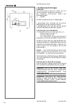
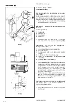
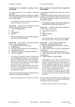
Fig. iii-4 (1)
Fixation du dispositif de chargement
sur la machine (vue de haut)
1
Dispositif de chargement
2
Clip
3
Boulon de fixation
4
Machine
•
Insérer le dispositif de chargement par le haut dans
les boulons de fixation et enfoncer le clip
(
A-B
).
Fig. iii-4 (2)
Raccordement du dispositif de
chargement - Montage du garde–pieds
1
Dispositif de chargement monté sur la machine
2
Chariot coulissant
3
Garde–pieds, doit être monté sur le dispositif de
chargement
4
Alimentation en air comprimé (raccord à vis)
5
Support pour garde–pieds, prémonté sur le dispositif
de chargement
6
Collier de fixation pour garde–pieds
•
L’alimentation en air comprimé s’effectue par
l’intermédiaire du tuyau d’air comprimé joint à la
machine. La pression de service est de 8 bars. Un
détendeur intégré est préréglé en usine à cette valeur
et ne doit pas être modifié par le client. La pression
d’alimentation devrait être de 8 bars au minimum et
ne doit en aucun cas dépasser 15 bars.
•
Insérer le garde–pieds joint dans le sens de la flèche
(2, Fig. iii-4) dans les brides de blocage, ajuster
l’écart de 30 mm comme indiqué et serrer les colliers
de fixation.
Pour des raisons de transport, le panneau latéral de la
colonne est monté vers l’intérieur (crochet pour
stockage du moyen de centrage).
•
Dévisser le panneau latéral, tourner et revisser.
Installing the pneumatic loading device
(OPTIONAL).
The loading device for truck wheels is provided
separately.
With the loading device wheels weighing up to 250 kg
can be pneumatically lifted and positioned exactly on
the clamping adaptor.
•
The loading device has to be mechanically attached
(positive locking) to the machine.
Fig. iii-4 (1)
Attachment of pneumatic loading
device to the machine (seen from the top)
1
Pneumatic loading device
2
Clip
3
Locating stud
4
Machine
•
Place the loading device over the locating stud from
above and insert the clip (
A-B
).
Fig. iii-4 (2)
Connection of pneumatic loading
device - mounting the foot guard
1
Loading device fitted to the machine
2
Sliding carriage
3
Foot guard, has to be fitted to the loading device
4
Air connection (union)
5
Holder for foot guard, pre–fitted to loading device
6
Clamp for foot guard
•
The air supply is provided by means of the pneumatic
hose supplied with the machine. The service pressure
is 8 bar. An integrated pressure reducer is factory–
adjusted to this value and must not be changed by
the customer. The line pressure should be at least 8
bar and must never exceed 15 bar.
•
Slide the foot guard supplied with the machine into
the clamps in the direction shown by the arrow (2,
Fig. iii-4), adjust the distance of 30 mm as shown
and tighten the clamps.
For ease of transport the column side panel is facing
inwards (hook for storage of adaptors).
•
Unscrew the side panel, turn it round and re–fasten.
Summary of Contents for EEWBUS732A
Page 102: ...102 geodyna 980L ...
Page 117: ...117 geodyna980L ...
Page 118: ...118 geodyna980L BLANK PAGE ...
Page 119: ...119 geodyna980L BLANK PAGE ...

