29
Utilisation
Manuel d’Utilisation
Operator’s Manual
Operation
geodyna 980L
geodyna 980L
5.1.1
Serrage d’une roue pour camion
La machine est équipée en usine d’un dispositif de
serrage pour camionnettes. Le cône de centrage
correspondant est adapté pour des diamètres de trou
central de 120 à 174 mm.
Les cônes de centrage pour serrer les roues de camion
ne sont pas compris dans le volume de livraison:
Option A: Kit standard
avec cône de centrage pour
diamètre de trou central de 198 à 225 mm
et 270 à 286,5 mm.
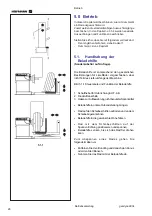
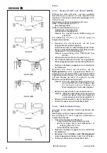
Fig. 5.1-2
Serrage d’une roue pour camion avec
bride d’appui et cône de centrage
1
Bride d’appui pour camion
2
Jante
3
Cône de centrage pour diamètre de trou central 198
- 225 mm o 270 mm - 286,5 mm
4
Ecrou à oreilles pour serrage
Option B: Kit professionnel
avec étoile de centrage
à 4 ou 5 bras ainsi que 5 boulons.
Serrage d’une roue pour camion avec bride
d’appui et etoile de centrage
Fig. 5.1.5-2.
1
Bride d’appui pour camion
2
Jante
3
Etoile de centrage
4
Ecrou à oreilles pour serrage
Remarque
Pour serrer une roue PL avec bride d’appui et étoile de
centrage, la bride de centrage PL doit être tournée.
Processus de serrage
•
Avant de serrer la roue, vérifier que le trou central ne
présente ni ébarbure ni déformation (ex: uniformément
rond) et que la surface de contact de la roue est
propre et intact.
•
Sélectionner le dispositif de centrage et le préparer en
fonction de la roue à équilibrer (Fig. 5.1-2 et 5.1-3).
•
Positionner la roue sur le moyen de serrage (Fig.
5.1-1) à l’aide du dispositif de chargement.
•
Fixer le cône ou l’étoile de centrage et serrer
légèrement la roue à l’aide de l’écrou à oreilles.
•
Descendre le dispositif de chargement jusqu’à ce
que la roue puisse tourner librement.
•
Tout en poursuivant le serrage, tourner la roue
légèrement de façon constante et continuer à serrer
l’écrou à oreilles. Cela permet de serrer la roue sans
la coincer d’un côté et pour qu’elle soit bien alignée
par rapport au cône ou à l’étoile de centrage, de sorte
qu’elle tourne sans à–coups après avoir été serrée.
Remarque
Pour obtenir un bon résultat d’équilibrage, il est important
de maintenir les moyens de serrage constamment
propres et de les stocker comme il se doit quand ils ne
sont pas utilisés.
5.1.1
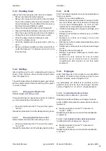
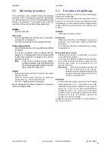
Clamping a truck wheel
The machine is delivered with an adaptor for light–truck
wheels. The relative centring cone is suitable for pitch
circles of 120 - 174 mm.
Clamping accessories for truck wheels are optional extras,
but they are indispensable for balancing the following types
of wheel:
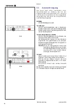
Option A: Truck standard
kit with centring cone for
pitch circle 198 - 225 mm and 270 - 286.5
mm.
Fig. 5.1-2 Clamping a truck wheel using an adaptor
and a centring cone
1
Truck wheel flange
2
Rim
3
Centring cone for pitch circle 198 - 225 mm or
270 - 286.5 mm
4
Wing nut for clamping
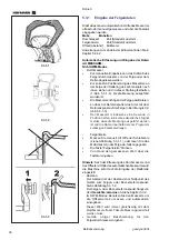
Option B: Truck professional
kit with 4-arm and 5-
arm star and a 5 column flange.
Fig. 5.1-3 Clamping a truck wheel using an adaptor
and a centring star
1
Truck wheel flange
2
Rim
3
Centring star
4
Wing nut for clamping
Note
To clamp a truck wheel with flange and centring star,
the golden truck wheel flange has to be used.
Clamping procedure
•
Before clamping the wheel, check that the centre
bore is machined sufficiently accurately and not
deformed (e.g. uniformly round) and that the contact
surface of the wheel (central rim disc) is clean and
intact.
•
Select and prepare a suitable clamping adaptor for
the wheel to be balanced (Fig. 5.1-2 and 5.1-3).
•
Position the wheel bore at the centre of the clamping
adaptor (Fig. 5.1-1).
•
Fit the cone or centring star and partly tighten the
wheel with the wing nut.
•
Lower the loading device until the wheel can rotate
freely.
•
As the wheel is further clamped continue rotating
the wheel slightly and further tighten the wing nut. In
this way the wheel will be aligned evenly with the
centring cone or centring star and will run smoothly
when clamped.
Note
For perfect balancing results the adaptors must always
be kept clean and stored correctly when not in use.
Summary of Contents for EEWBUS732A
Page 102: ...102 geodyna 980L ...
Page 117: ...117 geodyna980L ...
Page 118: ...118 geodyna980L BLANK PAGE ...
Page 119: ...119 geodyna980L BLANK PAGE ...

