47
Utilisation
Manuel d’Utilisation
Operator’s Manual
Operation
geodyna 980L
geodyna 980L
5.3.2.5
Balancement interne
Application d'une pièce à l'intérieur du pneu.
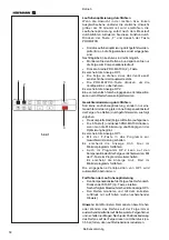
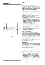
Presser sur la touche "
F
" pour activer la fonctionnalité,
donc presser la touche "
INT
", voir Figure 5.3.2.5-1.
Indicateur de direction gauche - "
" Il sera affiché,
pour indiquer qu'on doit insérer la donnée du diamètre
extérieur du pneu. Le valeur il sera affiché dans le viseur
de droite.
Remarque:
La procédure est le même comme
pour balancement statique; la seule
différence qui est que vous avez besoin
d'introduire le diamètre du pneu externe
pour calculer
les masses
.
5.3.3
Lancement roue
Les paramètres de la roue et du type de jante utilisée
doivent avoir été préalablement saisis.
•
Abaisser le carter de roue à la position horizontal.
Le moteur démarre et la roue commence à tourner.
Les roues doivent tourner vers la droite en ayant comme
point d’observation le côté du montage de la roue.
La mesure est terminée lorsque les indicateurs de
direction s’allument. L’unité émettra un bip sonore. Le
frein entrera en fonction automatiquement et la roue
s’arrêtera à la correcte position de pose de la masse
pour le plan de gauche.
La/les masses à poser est/sont indiquée(s) sur
l’affichage. Pour un affichage au gramme près, Appuyer
sur la touche Fine.
•
Soulever le carter de roue, en le portant en position
verticale.
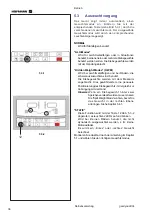
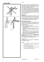
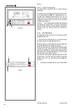
5.3.2.5
Internal Balancing
Application of a patch inside a tyre.
To activate the procedure press key “
F
” (1) then the
“
INT
” (2) key, Figure 5.3.2.5-1. The left-hand display
shows the text "
", which means you must enter
the external tyre diameter which will be shown on the
right-hand display.
Note:
The procedure is the same as for static
balancing
; the only difference being that
you need to enter the external tyre
diameter in order to calculate the weight.
5.3.3
Spinning the Wheel
The wheel data must be acquired and the type of rim to
be used must be entered.
•
Lower the tilting frame to its horizontal position.
The motor starts up and the wheel spins.
Wheels must turn towards the right, seen from the side
of the unit on which they are mounted.
The measurement is completed as soon as the direction
indicators light up. The unit beeps. The brake will be
applied automatically and the wheel will stop in the
correct left plane weight application position.
The weight(s) to be applied will be shown on the display.
For higher precision, select Fine.
•
Lift the wheel guard to its vertical position.
Summary of Contents for EEWBUS732A
Page 102: ...102 geodyna 980L ...
Page 117: ...117 geodyna980L ...
Page 118: ...118 geodyna980L BLANK PAGE ...
Page 119: ...119 geodyna980L BLANK PAGE ...

