59
Utilisation
Manuel d’Utilisation
Operator’s Manual
Operation
Une correction ultérieure n’est plus possible.
•
Démonter le pneu et serrer la jante pour effectuer
une lancée de compensation.
•
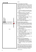
Appuyer sur la touche
PRO-MATCH
(2).
L’affichage OP.1 apparaît alors.
•
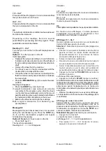
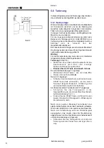
Tourner la jante jusqu’à ce que la valve soit
exactement perpendiculaire à et au–dessus de
l’arbre principal.
•
Appuyer sur la touche
PRO-MATCH
pour mettre la
position de la valve en mémoire.
L’affichage OP.2 apparaît alors.
Une fausse entrée de la position de la valve peut être
corrigée en répétant cette opération.
Effectuer une minimisation des masses
Si ce n’est pas l’optimisation, mais seulement la
minimisation des masses qui doit être effectuée (donc
sans lancée de compensation de la jante sans pneu),
procéder comme suit :
•
Assembler l'ensemble pneu / jante.
•
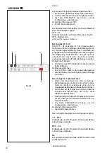
S'il se commence la minimisation de manière
indépendante de l'optimisation, appuyer sur la touche
F
(1) et de suite la touche
POUR-MATCH
(2).
L’affichage OP.1 apparaît alors.
•
Appuyer sur la touche
F
(1) pour commuter au
programme de minimisation.
L’affichage UN.3 apparaît alors. Poursuivre alors le
déroulement du programme de minimisation.
Même au niveau de l’affichage OP.2, la lancée de
compensation de la jante peut être omise.
•
Poursuivre dans le programme en appuyant sur la
touche
F
(1).
L’affichage passe alors à UN.4.
•
Poursuivre le déroulement du programme de
minimisation.
La position de valve de OP.1 reste entrée.
Poursuite du programme d’optimisation
•
Appuyer sur la touche
START
(3) pour initialiser la
lancée de compensation de la jante sans pneu.
Après la lancée de mesure, OP.3 est affiché.
•
Monter le pneu et le gonfler correctement (voir la
remarque ci–dessous).
Remarque
: Pour le montage, le démontage, le
déplacement ou le renversement du pneu
sur la jante, appliquer toujours une quantité
suffisante de lubrifiant sur les talons du
pneu, les rebords de jante et les assises
du pneu. Chaque fois que la position du
pneu a été modifiée par rapport à la jante,
gonfler le pneu à une surpression
(d’environ 3,5 bars) puis le dégonfler à la
pression de service.
Veiller à ce que le filet de centrage soit en position correcte.
•
Monter l’ensemble pneu/jante sur l'équilibreuse.
•
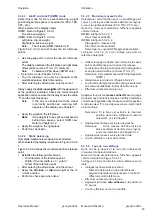
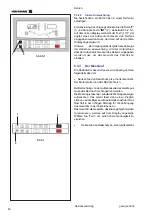
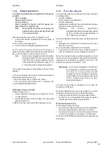
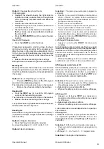
Press the
PRO-MATCH
key (2).
The OP.1 reading appears.
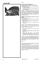
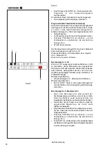
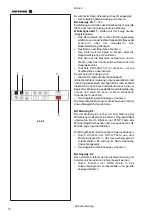
In all figures in which the valve symbol appears on the
edge of the rim, shift the tyre on the rim then press
the PRO-MATCH key (2) to set the valve position
(exactly perpendicular to and above the main shaft).
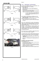
•
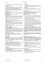
Readjust the rim so that the valve is exactly
perpendicular to and above the main shaft.
•
Press the
PRO-MATCH
key (2) to acquire the valve
position.
The OP.2 reading appears.
An incorrect valve position entry can be corrected
afterwards.
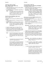
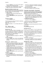
Weight minimisation
If no optimisation, but only weight minimisation (i.e.
without compensation run for the rim without tyre),
proceed as follows:
•
Clamp the complete wheel (rim and tyre).
•
Press
F
(1) +
PRO-MATCH
(2) if minimisation is
starter separately from optimisation.
The OP.1 reading appears.
•
Press the
F
key (1) to activate the weight
minimisation program.
The Un.3 reading appears. Run the minimisation
program.
•
With program OP.2 the rim compensation run can
still be omitted. Go to the next step in the program
by pressing the
F
key (1).
The UN.4 reading appears.
•
Continue the minimisation program.
The valve position entered with OP.1 is automatically
used.
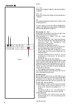
Continuing balancing optimisation
•
Press the
START
key (3) to start the rim
compensation run without the tyre.
After the measuring run the OP.3 reading appears.
•
Mount the tyre and inflate correctly (see note below).
Note
For mounting and demounting (tyre changer) and tyre
turning or readjustment on the rim, always apply a
sufficient amount of tyre lubricant on the tyre beads
and the rim edges and shoulders. Each time the
position of the tyre is changed on the rim, inflate the
tyre to overpressure (approx. 3.5 bar) then deflate to
correct tyre pressure.
Make sure the centring line is correctly positioned on
the tyre bead.
•
Clamp the wheel.
Summary of Contents for EEWBUS732A
Page 102: ...102 geodyna 980L ...
Page 117: ...117 geodyna980L ...
Page 118: ...118 geodyna980L BLANK PAGE ...
Page 119: ...119 geodyna980L BLANK PAGE ...

