5
Operation manual geodyna 2350 - 9413 126
Installation of the machine
687
170
458
32
590
75
2
3
4
5
6
SW 13
1
2
2.
Installation of the machine
When choosing the site, Health and Safety at Work regulations
and the regulations on working environment should be taken
into account.
The wheel balancers can be installed on any firm and level
ground. For the weight and space requirement of the machines
refer to § 15. Technical data. For installation on an upper floor,
check and observe the permissible load capacity of the floor.
It is recommended, though not absolutely necessary, that the
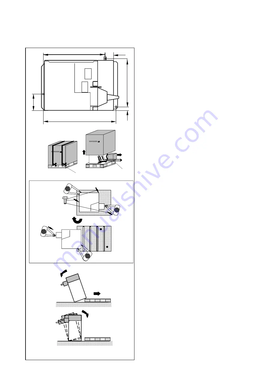
machine be secured to the floor. For this purpose three holes
(Fig. 2)
are provided in the base of the machine by which the
latter is fixed on the floor with 3/8” anchor bolts. Fig. 2 shows the
center-to-center distance of the holes. Make sure that the ma-
chine has a stable position, i.e. that it is supported on
three
seatings. If not, ensure three-point contact on ground by insert-
ing appropriate spacers between the floor and machine base.
For transport the wheel balancer is provided with special pack-
ing (on pallet).
2.1
Unpacking the machine
The machine should be unpacked by two persons.
Note
When unpacking the machine make sure that the pedal fitted on
the machine base and the whole pedal assembly is not dam-
aged.
D
Cut the strips of the packing
(Fig. 3, item 1)
, lift off the
packing and set aside the small parts packed in the sep-
arate small box
(Fig. 3, item 2)
.
D
Use a 1/2” wrench to unscrew the three hexagon screws
which hold the machine on the pallet
(Fig. 4, arrows)
.
D
Lift the machine by tube of the vibratory system and turn
around by 180 degrees on the pallet
(Fig. 4)
.
D
Then lower one side of the machine laterally on the floor
(Fig. 5)
.
D
Remove the pallet from underneath the machine and
gently lower the entire machine onto the floor
(Fig. 6)
.


