


Calibration instructions
geodyna 6300
Page 2 of 8
Date 2 Oct 2001
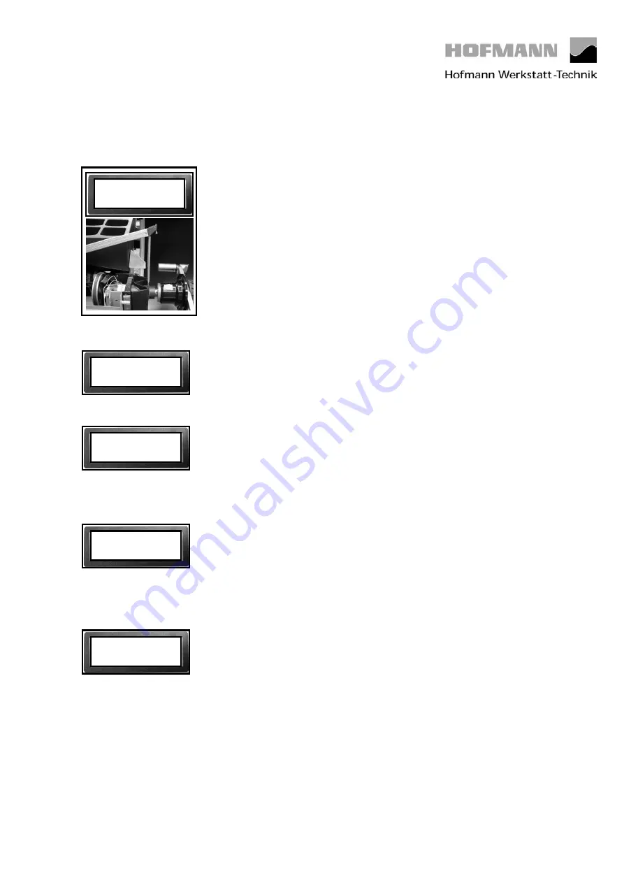
The following reading appears:
Raise the gauge arm, apply the calibration tip of the diameter calibration rod
into the calibration groove of the board of the vibratory system and the
calibration tip of the gauge arm into the recess at the lower end of the
calibration rod. Pull out the gauge arm until the calibration rod is in vertical
position.
Press the C key to store the value.
The following reading appears:
Step no. 5 has no function yet.
The following reading appears:
Raise the gauge arm and pull out at least 3 times
slowly
until it clamps. After
each clamping hold the gauge arm for at least 1 second in the instantaneous
clamping position before repeating this procedure. When the gauge arm had
been pulled out and clamped 3 times, the reading proceeds automatically with
step no. 7.
The following reading appears:
Pull out the gauge arm at least 7 times with increased
constant speed
until it
clamps. After each clamping hold the gauge arm for at least 1 second in the
instantaneous clamping position before repeating this procedure. When the
gauge arm had been pulled out and clamped 7 times, the reading proceeds
automatically with C- -.
The following reading appears:
Calibration is completed and must be stored by entering C90
.
4. 0,16
5.
6.
7.
C - -


