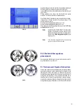
25
11.1-2
11.1-3
1
2
3
11.1-4
F1
F3
F4
F5
WHEEL No. 1
•
Mount the wheel on the balancer shaft.
•
Perform the run.
The balancer completes the optima program readings,
then the rear laser scanner scans the tread to acquire
the conicity indices.
Note
: The overall cycle time is increased by this
operation.
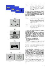
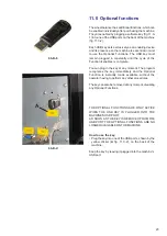
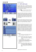
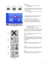
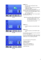
The icon indicating the tread conicity angle appears on
the OPTIMA ENTRY screen page (Fig. 11.1-2).
The meanings of the icons are as follows:
1
) Tread conicity reading with pull towards LEFT.
2
) Tread conicity reading with NEUTRAL pull.
3
) Tread conicity reading with pull towards RIGHT.
•
Balance the planes and make any corrections
suggested by
optima
.
•
Remove the wheel from the balancer.
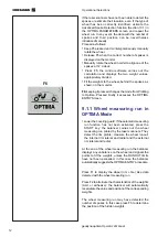
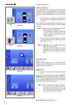
When you remove the wheel, the screen shows a
number and a colour assigned to the wheel, useful for
identifying it until the procedure is complete (Fig. 11.1-
3).
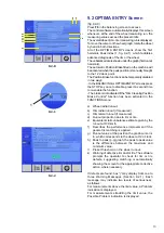
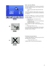
From this moment the keys in the control bar have the
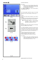
following functions (Fig. 11.1-4):
Key
F1
EXIT the Set of Wheels program; the data acquired up
to this point is definitively deleted. The machine returns
to the OPTIMA ENTRY screen and stands by for further
commands.
Key
F3
ENTER a wheel which can be mounted only on the left
of the vehicle; tyres with mandatory direction.
Key
F4
ENTER a wheel without direction constraints, which
can therefore be used on either side of the vehicle.
Key
F5
ENTER wheels which can only be mounted on the right
of the vehicle; tyres with mandatory direction.
Summary of Contents for geodyna optima
Page 1: ...geodyna optima Additional instructions Wheel balancer ...
Page 2: ......
Page 55: ...53 geodyna optima Operator s Manual Manuel d Utilisation Note Note page La página de la nota ...
Page 56: ...54 Electrical diagram ...
Page 57: ...55 Electrical diagram ...
Page 58: ...56 Electrical diagram ...
Page 59: ...57 Electrical diagram ...
Page 61: ...Note page ...

