26
Operational Selections
geodyna optima
Operator’s Manual
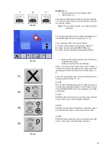
11.1-5
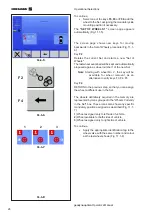
11.1-6
F2
F4
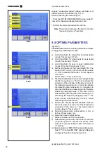
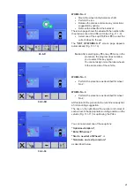
11.1-7
1
2
3
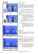
11.1-8
To continue,
•
Select one of the keys
F3
,
F4
or
F5
to add the
wheel to the Set, assigning the mandatory side
mounting position if necessary.
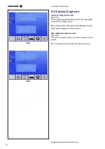
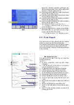
The
"SET OF WHEELS 1"
screen page appears
automatically (Fig. 11.1-5).
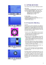
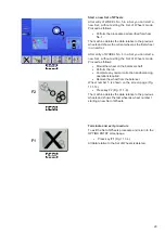
The screen page shows new keys, for moving
backwards in the Set of Wheels procedure (Fig. 11.1-
6):
Key
F2
Deletes the current Set and starts a new "Set of
Wheels".
The last wheel examined will be kept and automatically
proposed again as wheel number 1 of the new Set.
Note
: Starting with wheel No. 2, the key will be
available for wheel removal, as an
alternative to entry keys F3, F4, F5.
Key
F4
RETURN to the previous step, so that you can assign
the wheel a different use in the Set.
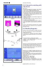
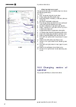
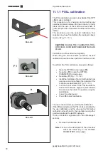
The wheels definitively acquired in the memory are
represented by icons grouped in the "Wheels Currently
in the Set" box. These icons also show any specific
mandatory position assigned as described (Fig. 11.1-
7):
1
) Wheel assigned only to left side of vehicle.
2
) Wheel available for both sides of vehicle.
3
) Wheel assigned only to right side of vehicle.
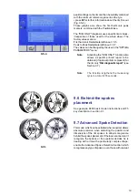
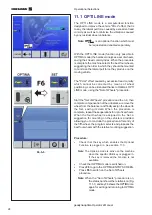
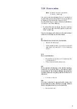
To continue,
•
Apply the appropriate identification tag to the
wheel valve, with the same number and colour
as the last wheel shown (Fig. 11.1-8).
Summary of Contents for geodyna optima
Page 1: ...geodyna optima Additional instructions Wheel balancer ...
Page 2: ......
Page 55: ...53 geodyna optima Operator s Manual Manuel d Utilisation Note Note page La página de la nota ...
Page 56: ...54 Electrical diagram ...
Page 57: ...55 Electrical diagram ...
Page 58: ...56 Electrical diagram ...
Page 59: ...57 Electrical diagram ...
Page 61: ...Note page ...

