5
1.4-1
1.4 Description of function
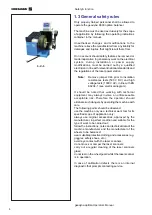
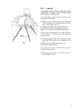
The wheel data detection is carried out automatically
and with no contact by 3 laser scanners, with
integrated CCD. The 6800 optima balancer calculates
the co-ordinates of the optimal positions for the
application of balancing counter-weights.
The geodyna 6800 optima balancer can be used to
determine geometric information relative to rim
deformations (deviations of the axis in respect of its
rotation axis, commonly referred to as RUNOUT); to
determine geometric information relative to tire
deformations (deviations of the axis in respect of its
rotation axis). This information is useful for an accurate
diagnosis of the wheel behaviour as well as providing
the operator with useful indications to minimise the
effects of these deformations.
The geodyna 6800 optima balancer is able to
automatically determine the unbalance of the rim or
of the wheel in respect of its rotation centre. At the
end of the measuring run the control software carries
out a matching, that consists in corresponding the top
part of the tire with the bottom part of the rim. The
balancer analyses the overall state of the wheel and
prompts for any repairs required.
The geodyna 6800 optima balancer carries out two
types of
runout
:
1)
radial (on the radius);
2)
lateral (on the lateral shift).
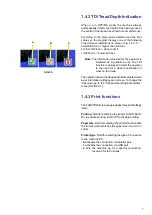
The geodyna optima balancer also has the TDI (
Tread
Depth Indication
) system, which provides a general
indication of tread wear. This function is only active in
OPTIMA mode.
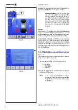
The geodyna 6800 optima balancer can operate in
three distinct modes:
a)
MANUAL
b)
PROFILING
c)
OPTIMA
MANUAL
The machine guarantees the basic functions,
suggesting the position and value of the weights to
apply to the rim. The use is similar to the standard
models; balancers fitted only with the left detecting
device. The MANUAL mode is activated through the
functions menu.
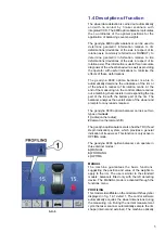
PROFILING
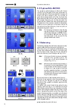
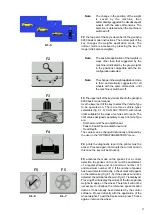
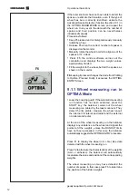
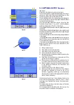
This mode is identifiable on the monitor with the symbol
displayed in fig. 1.4-1 detail 1. The control software
automatically acquires the wheel dimensions during
the measuring run. During the normal measurement
cycle the laser scanner automatically sample the rim
shape (internal and external). The machine optically
Summary of Contents for geodyna optima
Page 1: ...geodyna optima Additional instructions Wheel balancer ...
Page 2: ......
Page 55: ...53 geodyna optima Operator s Manual Manuel d Utilisation Note Note page La página de la nota ...
Page 56: ...54 Electrical diagram ...
Page 57: ...55 Electrical diagram ...
Page 58: ...56 Electrical diagram ...
Page 59: ...57 Electrical diagram ...
Page 61: ...Note page ...


