NOTE GENERALI
Macchina equilibratrice per ruote di vetture, autocarri, veicoli commerciali leggeri, fuoristrada, moto e
scooter.
La progettazione e la costruzione della macchina sono eseguite in ottemperanza alle norme
CE come da modulo allegato, tenendo conto dell’uso normale e di quello ragionevolmente prevedibile.
La macchina è stata progettata e costruita esclusivamente per l’utilizzo citato nel manuale d’uso.
Non è consentito, per nessuna ragione, utilizzarla per scopi o modalità differenti.
EMISSIONE DI RUMORE AEREO
La rumorosità della macchina, misurata a vuoto, si mantiene su livelli costantemente inferiori a 70 dB(A).
MOVIMENTAZIONE
La movimentazione, da eseguirsi quando la macchina è ancora fissata al bancale di legno, deve essere
eseguita da personale adeguatamente addestrato ed equipaggiato con i Dispositivi di Protezione Individuale.
ATTENZIONE
MOVIMENTARE CON MOLTA ATTENZIONE LA MACCHINA SOLLEVANDOLA IL MINIMO NECESSARIO ED EVITANDO
OSCILLAZIONI, PENDOLAMENTI E SBILANCIAMENTI PERICOLOSI.
Prima di sollevare l’apparecchiatura, con un carrello elevatore o un transpallet, accertarsi che le forche
siano adeguatamente posizionate e che sporgano sul lato opposto.
RIMOZIONE DEL BANCALE
Per le operazioni di sollevamento e deposito a terra della macchina, predisporre un’area delimitata e
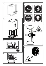
adeguata, con pavimentazione a fondo piano. Per la rimozione del bancale, tagliare le regge (1), sfilare
il cartone e rimuovere la scatola della dotazione e l’eventuale protezione (2); successivamente, togliere
le viti che lo fissano alla macchina (3) e sollevarla collocandola correttamente nella posizione finale (4).
ATTENZIONE
LA MOVIMENTAZIONE ED IL SOLLEVAMENTO MANUALE DELLA MACCHINA DEVONO ESSERE EFFETTUATI CON
L’AUSILIO DI UN CARRELLO ELEVATORE; FARE LEVA SUL BASAMENTO IN CORRISPONDENZA DEI 3 PUNTI DI
APPOGGIO (3); ALTRI PUNTI, QUALI AD ESEMPIO LA TESTA O IL RIPIANO PORTA-ACCESSORI, NON DEVONO
ESSERE FORZATI IN ALCUN CASO.
CARATTERISTICHE AMBIENTALI
L’apparecchiatura deve essere collocata rispettando le seguenti condizioni:
▪
90% di umidità relativa massima e temperatura compresa fra + 5 ÷ + 45 °C (41 ÷ 113 °F);
▪
rispetto delle norme di protezione antincendio;
▪
agevole accessibilità frontale, laterale e posteriore per non interferire con le operazioni di assistenza
o manutenzione periodica e adeguata circolazione d’aria;
▪
totale assenza di polveri o gas corrosivi/esplosivi nell’ambiente ove l’apparecchiatura è installata;
▪
assenza di vibrazioni;
▪
buona illuminazione dell’area in cui è collocata la macchina;
▪
superficie di appoggio piana, non elastica e sempre in corrispondenza dei tre piedi, tenendo presen
te
che dislivelli della pavimentazione possono compromettere la qualità della misura.
ATTENZIONE
NEL CASO IN CUI, ALL’ATTO DELL’INSTALLAZIONE, VENISSERO RISCONTRATE CONDIZIONI AMBIENTALI
DIVERSE DA QUELLE PRESCRITTE, O SE LE STESSE DOVESSERO SUBIRE VARIAZIONI NEL TEMPO, PRIMA
DELL’USO DELLA MACCHINA DOVRÀ ESSERE IMMEDIATAMENTE CONTATTATO IL COSTRUTTORE PER LE
VERIFICHE DEL CASO.
COLLEGAMENTO ELETTRICO
Prima di eseguire qualsiasi operazione, è necessario assicurarsi che il quadro elettrico generale, a
cui viene collegata l’apparecchiatura, abbia una connessione sicura al circuito di terra e un’adeguata
protezione, come richiesto dalla normativa in vigore nel Paese ove l’apparecchiatura è installata. La
presa a cui la macchina verrà collegata dovrà essere provvista di un interruttore di sicurezza ad azione
lenta, tarato a 4 A (230V) o 8A (115V) e dovrà essere dimensionata in modo da sopportare la potenza
assorbita, fino ad un massimo di 1.1 kW. Controllare che la tensione di rete e la frequenza corrispon-
dano ai valori indicati nella targa dell’apparecchiatura. La macchina viene fornita con cavo monofase,
a cui va collegata una spina conforme alle normative. Nel caso non si possa evitare di utilizzare una
prolunga, la sezione dei fili non dovrà essere inferiore a 2,5 mm
2
. La prolunga va posizionata in modo
che non costituisca pericolo o intralcio.
ATTENZIONE
IL COLLEGAMENTO ALLA RETE MONOFASE DEVE ESSERE EFFETTUATO TRA FASE E NEUTRO, MAI TRA FASE
E TERRA! È FATTO DIVIETO ASSOLUTO DI ACCENDERE LA MACCHINA SE PRIVA DI UN EFFICACE COLLEGA-
MENTO DI MESSA A TERRA, ESEGUITO SECONDO LE SPECIFICHE TECNICHE PREVISTE DALLE NORMATIVE
IN VIGORE. IN OGNI CASO, I COLLEGAMENTI ELETTRICI DEVONO ESSERE ESEGUITI ESCLUSIVAMENTE DA
PERSONALE TECNICO SPECIALIZZATO, ADEGUATAMENTE ISTRUITO AD OPERARE IN CONFORMITA’ ALLA
DIRETTIVA EUROPEA CEI EN 50110-1 (NFPA70E-2004 SECTION 400.11).
COLLEGAMENTO PNEUMATICO
Nel caso la macchina sia dotata di impianto pneumatico, è necessario alimentarla con aria compressa
7/10 bar. L’attacco per l’aria compressa è posizionato sul retro della macchina; l’aria compressa deve
essere tassativamente pulita ed asciutta. Il collegamento delle tubazioni e della raccorderia deve
essere effettuato correttamente da personale adeguatamente addestrato.
DISPOSITIVI DI PROTEZIONE INDIVIDUALE (DPI)
ATTENZIONE
DURANTE LE OPERAZIONI DI INSTALLAZIONE E UTILIZZO DELLA MACCHINA, È FATTO DIVIETO ASSOLUTO
DI OPERARE SENZA I DISPOSITIVI SOTTOINDICATI.
Le seguenti segnalazioni riassumono i dispositivi di protezione da indossare: calzature antinfortunistiche
con suola in gomma e puntarinforzata (norma EN345)(ANSI Z41.1-1991) (OSHA, 1910.136), guanti di
protezione (norma EN388) (ANSI/ISEA 105-2005) (OSHA,1910.138), occhiali (norma EN166 1F) (ANSI Z87.1)
(OSHA,1910.133) e indumenti da lavoro (EN510) (OSHA,1910.132) (5). Il personale preposto ad operare
e/o transitare in prossimità della macchina non deve indossare indumenti con maniche larghe, né lacci,
cinture, braccialetti o altre parti che possano essere causa di pericolo.
Per lo stesso motivo, eventuali capelli lunghi dovranno essere raccolti.
RISCHI RESIDUI
Per rischio residuo si intende un potenziale pericolo, impossibile da eliminare o parzialmente eliminabile,
che potrebbe provocare danni all’operatore se intervenisse con metodi e pratiche di lavoro non corrette.
▪
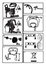
Prestare attenzione alla posizione delle mani nelle zone indicate in figura perchè, durante il bloccaggio
della ruota sul mandrino, si potrebbe subire lo schiacciamento delle dita (6).
▪
Durante le operazioni di carico scarico del pneumatico, prestare attenzione all’accidentale
schiacciamento dei piedi (7).
▪
Per le macchine munite di sollevatore, non sostare nell’area di lavoro poichè, durante le fasi di
salita e discesa dello stesso, potrebbe esserci rischio di schiacciamento (8/9).
USO
Per accendere l’equilibratrice premere l’interruttore posto sul fianco sinistro dell’apparecchiatura.
ATTENZIONE
IL SISTEMA DI CENTRATURA (FLANGIA) DEVE ESSERE COSTANTEMENTE PULITO; EVENTUALI RESIDUI DI
SPORCO POSSONO INFLUIRE SULLA PRECISIONE DELL’EQUILIBRATURA.
▪
Infilare il cono sull’albero e serrare la ruota mediante la ghiera di fissaggio o il manicotto in dotazione (10).
▪
Impostare la DISTANZA “a “ esistente tra il fianco interno della ruota e la macchina. Per questa
operazione utilizzare l’apposito calibro presente a bordo macchina (11).
▪
Impostare il DIAMETRO nominale “d” indicato sul pneumatico. Nel caso la macchina fosse dotata di
calibro automatico, estrarlo e posizionarlo esattamente dove si vorrà applicare il peso di correzione
(12). In questo caso le misure vengono memorizzate automaticamente dopo segnalazione sul display.
▪
Impostare la LARGHEZZA nominale, normalmente riportata sul cerchio, oppure rilevare la larghezza
“b” con il calibro a compasso in dotazione (13). Non eseguire se la macchina è provvista di
rilevazione automatica della larghezza.
▪
Per effettuare il lancio abbassare la protezione paraspruzzi, ove presente, e premere il pulsante
START.
▪
Muovere la ruota manualmente fino all’indicazione della corretta posizione angolare sul fianco
in esame. Il display visualizza lo squilibrio rilevato (14).
▪
Applicare i pesi di correzione (14).
SMALTIMENTO
La direttiva comunitaria 2002/96/CE (US H.R. 2420), recepita in Italia dal decreto legislativo n. 151 del
25 luglio 2005, ha imposto ai produttori e agli utilizzatori di apparecchiature elettriche ed elettroniche una
serie di obblighi relativi alla raccolta, al trattamento, al recupero e allo smaltimento (15).
Per ulteriori informazioni consultare il manuale completo.
IT
EN
GENERAL NOTES
Wheel balancing machine for cars, trucks, pickup trucks, off-road vehicles, motorcycles and scooters.
The machine has been designed and constructed in compliance with the EC standards as indicated in the
attached form taking normal and reasonably foreseeable use into account.
The machine has been designed and constructed exclusively for the use described in the user manual.
It is not permitted to use the machine for different purposes or procedures for any reason whatsoever.
AIRBORNE NOISE EMISSION
The machine noise, measured with the machine empty, is constantly maintained at levels below 70 dB(A).
HANDLING
The machine must be handled by adequately trained persons equipped with Personal Protection Devices
while still tied to the wooden pallet.
WARNING
HANDLE THE MACHINE WITH GREAT CARE LIFTING IT ONLY THE MINIMUM NECESSARY AND AVOIDING
DANGEROUS OSCILLATION, SWINGING AND UNBALANCING.
Before lifting the machine with a lift truck or transpallet, make sure that the forks are properly posi-
tioned and protrude from the opposite side.
REMOVING THE PALLET
Prepare an adequate area with level flooring and mark it off before lifting the machine and positioning
it on the ground. To remove the pallet, cut the straps (1), remove the cardboard, the box of accessories
and any protection (2); then remove the screws that secure the machine on the pallet (3) and lift and
place it in its final position (4).
WARNING
MANUAL MACHINE HANDLING AND LIFTING MUST BE CARRIED OUT WITH THE AID OF A LIFT TRUCK. PRISE
ON THE BASE IN CORRESPONDENCE TO THE 3 SUPPORT POINTS (3); OTHER POINTS, SUCH AS THE HEAD
OR THE ACCESSORY TRAY MUST NOT BE FORCED IN ANY WAY.
AMBIENT CHARACTERISTICS
The machine must be positioned respecting the following conditions:
▪
90% relative humidity and maximum temperature between 5°C and 45°C (41°F and 113°F).
▪
In observance of the fire-fighting regulations.
▪
Easily accessible from the front, side and rear for service or periodic maintenance operations, and
adequate air circulation.
▪
Total absence of dust or corrosive/explosive gases in the environment where the machine is installed.
▪
No vibrations.
▪
Good lighting in the area where the machine is positioned.
▪
Flat non-resilient support surface and always standing on its three feet, bearing in mind that uneven
flooring may compromise the measurement quality.
WARNING
IF DURING INSTALLATION YOU FIND AMBIENT CONDITIONS DIFFERENT FROM THOSE PRESCRIBED, OR IF
THE AMBIENT CONDITIONS CHANGE OVER TIME, IMMEDIATELY CONTACT THE MANUFACTURER FOR AN
INSPECTION BEFORE USING THE MACHINE.
ELECTRICAL CONNECTION
Before carrying out any operation, check that the main electric cabinet to which the machine is connected
is securely connected to the earth circuit and adequately protected as required by the regulations in
force in the country where the machine is installed. The power outlet to which the machine will be
connected must be fitted with a slow-action safety switch calibrated to 4 A (230V) or 8A (115V) and must
be dimensioned to be able to withstand the power absorbed up to a maximum of 1.1 kW. Check that the
mains voltage and frequency correspond to the values indicated on the machine identification plate.
The machine is supplied with a single-phase cable to which a plug conform to the standards must be
connected. If you cannot avoid using an extension cable, the cross-section of the wires may not be less
than 2.5 mm
2
. The extension must be positioned in such a way that it does not pose a risk or hindrance.
WARNING
THE CONNECTION TO THE SINGLE-PHASE SYSTEM MUST BE BETWEEN PHASE AND NEUTRAL AND NEVER
BETWEEN PHASE AND EARTH! IT IS STRICTLY PROHIBITED TO TURN ON THE MACHINE IF IT DOES NOT
HAVE AN EFFICIENT EARTH CONNECTION IN ACCORDANCE WITH THE TECHNICAL SPECIFICATIONS SET
OUT IN THE REGULATIONS IN FORCE. IN ANY EVENT, THE ELECTRICAL CONNECTIONS MUST EXCLUSIVELY
BE CARRIED OUT BY A SPECIALISED TECHNICIAN TRAINED TO OPERATE ACCORDING TO CEI EN 50110-1
(NFPA70E-2004 SECTION 400.11).
PNEUMATIC CONNECTION
If the machine is equipped with a pneumatic system, it must be fed with compressed air at 7/10 bar. The
compressed air connection is positioned on the rear of the machine; the compressed air must be perfectly
clean and dry. The pipes and pipe fittings must be connected properly by adequately trained persons.
PERSONAL PROTECTION DEVICES (PPD)
WARNING
DURING INSTALLATION AND USE OF THE MACHINE, IT IS STRICTLY PROHIBITED TO OPERATE WITHOUT THE
ABOVE MENTIONED PERSONAL PROTECTION DEVICES.
The following protection devices must be worn: safety shoes with rubber sole and reinforced tip (EN345
standard) (ANSI Z41.1-1991), protective gloves (EN388 standard) (ANSI/ISEA 105-2005) (OSHA,1910.138),
goggles (EN166 1F standard) (ANSI Z87.1) (OSHA,1910.133) and working clothes (EN510) (OSHA,1910.132)
(5). The persons that are to operate on and/or work in proximity of the machine may not wear clothes
with wide sleeves, laces, belts, bracelets or anything else that may pose a potential risk.
For the same reason, long hair must be tied up.
RESIDUAL RISKS
Residual risk means a potential risk impossible to eliminate or partially eliminatable, which might cause
injury to the operator if operating using improper working methods and practices.
▪
Pay attention to the position of your hands in the areas indicated in the figure, as there is a risk
of crushing your fingers during wheel locking on the spindle (6).
▪
While mounting or dismounting the tyre, pay attention to avoid accidentally crushing your feet (7).
▪
For machines equipped with lift, do not stand in the working area, as there is a risk of crushing
during ascent and descent of the lift (8/9).
USE
To turn on the wheel balancer press the switch on the left-hand side of the machine.
WARNING
THE CENTRING SYSTEM (ADAPTER) MUST BE KEPT CLEAN AT ALL TIMES; ANY DIRT RESIDUES MAY AFFECT
BALANCING PRECISION.
▪
Fit the cone on the shaft and tighten the wheel using the fastening ring nut or the collar provided (10).
▪
Set the DISTANCE “a” between the inside of the wheel and the machine. Use the relative gauge
on the machine for this operation (11).
▪
Set the nominal DIAMETER “d” indicated on the tyre. If the machine is equipped with an automatic
gauge, pull it out and position it exactly where you want to apply the correction weight (12).
In this case, the measurements are automatically stored after showing them on the display.
▪
Set the nominal WIDTH, normally indicated on the rim, or measure the width “b” using the calliper
gauge provided (13). Do not set the width if the machine is equipped with automatic width measurement.
▪
Lower the splash guard, when fitted, and press the START button to perform the spin.
▪
Move the wheel by hand up to the indication of the correct angular position on the side under
examination. The display shows the unbalance measured (14).
▪
Apply the correction weights (14).
DISPOSAL
The EC Directive 2002/96/EC (US H.R. 2420), implemented in Italy by Legislative Decree 151 of 25 July
2005, imposes a series of obligations on manufacturers and users of electric and electronic equipment
as regards their collection, treatment, recovery and disposal (15).
For further information, consult the complete manual.
Summary of Contents for Megaspin 420
Page 2: ......
Page 14: ...1 2 3 4 5 6 7 ...
Page 15: ...b a d b 8 9 10 11 12 13 14 15 ...
Page 16: ......


