30
5.1-6
5.1-7
5.1-5
5.1-8
Operator Manual
Note:
once the mount/demount head is
positioned properly, matching wheels
may be changed without having to reset
the head.
Note:
the plastic insert inside the mount/demount
tool must be periodically replaced. every
machine is equipped with several plastic
inserts (inside standard equipment box).
Follow the instructions included with the
replacement parts.
•
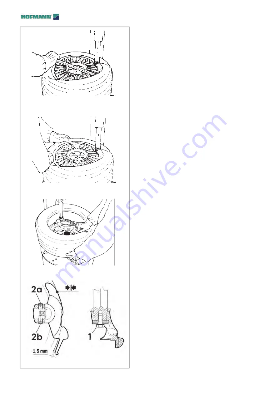
Insert the bead lifting tool under the bead and
over the support of the mount/demount tool. Lift
the bead onto the mounting finger. To facilitate
this operation, press with left hand on the bead in
position diametrically opposite to that of the tool. If
desired, the bead lifting tool can be removed after
lifting the bead onto the finger (Fig. 5.1-5).
•
Rotate the turntable clockwise and at the same time
push down on the tire sidewall to move the bead
into the drop-center of the rim (Fig.5.1-6).
•
Repeat the process for removing the lower bead.
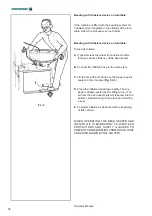
With left hand, lift the bead in position diametrically
opposite the tool to keep it in the drop center (Fig.
5.1-7). Move the swing arm aside and remove the
tire.
5.1.3
Tool Head Angular adjustment
(
Fig. 5.1-8
)
The tool is adjusted at the factory with an optimal angle
for most wheels used today. However, the angle can
be optimised for wheels with a diameter that differs
considerably from the standard.
To adjust the tool angle, proceed as follows:
1 Mount the rim for which the adjustment is required.
2 Loosen the lower screw (
1
).
3 Adjust the tool with the screws shown (
2a
and
2b
). Unscrew the screw
2a
or
2b
to rotate the tool,
respectively clockwise or counterclockwise.
4 Screw in the opposite screw to block the tool in the
desired angular position.
5 Tighten the lower screw (
1
) with a torque of 35 Nm.
Summary of Contents for Monty 1270 Smart
Page 54: ...54 B L A N K P A G E ...

