background image

14

5.0 Demounting Tube-type Tires

A. For breaking the bead operate as described for the
tubeless tires (from section 4.1.A to 4.1.B).

In this case the valve is part of the tube

WARNING
BE CAREFUL NOT TO DAMAGE THE TUBE DURING
THE BEAD-BREAKING OPERATION. THE VALVE
SHOULD BE OPPOSITE TO THE BLADE OF THE BEAD
BREAKER.

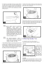
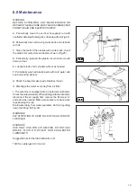
B. To demount the first bead, place the valve at 3 o’clock
position.

WARNING
DO NOT CATCH THE TUBE WITH THE BEAD LIFTING
TOOL, WHEN LIFTING THE BEAD ON THE MOUNTING
FINGER

After demounting the first bead remove the tube before
demounting the second bead, as described in section 4.1.

5.1 Mounting Tube-Type Tires

A. Proceed as described in section 4.2.A.
Do NOT lubricate the tube. Talc can be used to assist with
the tube positioning.

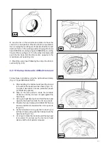
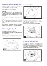
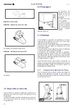
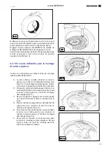
B. Mount the valve core and place the tube onto the tire to
confirm that the tube is of the correct size (Fig.5.0).

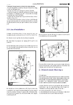
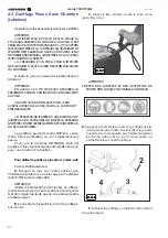
C. Inflate the tube slightly: if held with the index finger it
should bend a little (Fig.5.1).

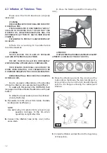
D. Mount the first bead as described in section 4.2.B.
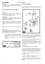
Put the tube inside the tire and secure the valve with the
chuck of the inflating hose (Fig. 5.2).
Mount the top bead following the directions above.

5.2 Inflating Tube-Type Tires

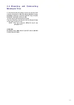
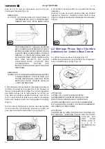
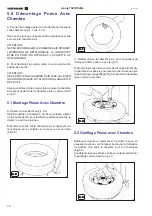
To inflate the tires unlock the rim and start inflating while
pressing the valve towards the inside. This is necessary
to avoid air pockets forming between tube and tire (Fig.5.3).
Ensure that the tire is correctly centered on the rim and
complete inflation as described in section 4.3.

341

5.0

5.0

5.0

5.0

5.0

342

5.1

5.1

5.1

5.1

5.1

343

5.2

5.2

5.2

5.2

5.2

537

5.3

5.3

5.3

5.3

5.3

Summary of Contents for monty 1520

Page 1: ...s Spare parts list Notice d utilisation Liste des pièces détachées Electric pneumatic tire changer for Car Motor Scooter and Motorcycle tires Démonte pneus électro pneumatique pour roues de Voitures Moto Scooter et Motocyclettes USA CANADA ...

Page 2: ...GERÄT Original language edition in ENGLISH ITALIAN Langue d origine de la publication ANGLAIS ITALIEN Originalausgabe in ENGLISH ITALIENISCH Pubblicazione di supporto al prodotto SMONTAGOMME publicación de soporte al producto DESMONTA RUEDAS Documentação de apoio ao produto MÁQUINA DE DESMONTAR PNEUS edizione di lingua originale in INGLESE ITALIANO edición original en idioma INGLÉS ITALIANO edição...

Page 3: ...e Tires Page 14 6 0 Maintenance Page 15 Spare Parts Page 31 Sommaire Page 3 1 0 Introduction Page 18 1 1 Destination d Emploi Page 18 1 2 Généralités Page 18 1 3 Règles Générales de Sécurité Page 18 1 4 Terminologie Page 19 1 5 Caractéristiques Techniques Page 19 1 6 Dimensions de la Machine Page 19 1 7 Accessoires d Origine Page 19 1 8 Dispositifs de Sécurité Page 20 2 0 Transport Page 20 2 1 Déb...

Page 4: ...ORIZED HOFMANN DEALER ANY MISUSE OR MODIFICATION OF THIS DEVICE OR OF ITS PARTS OR COMPONENTS NOT PREVIOUSLY AUTHORIZED BY THE MANUFACTURER WAIVE THE MANUFACTURER FROM ANY DAMAGE CONSEQUENT OR RELATED TO THE ABOVE MENTIONED MISUSES REMOVING OR BYPASSING SAFETY DEVICES OR WARNING LABELS OF THE MACHINE ISAVIOLATION OF THE SAFETY REGULATIONS THE USE OF THIS DEVICE IS ALLOWED ONLY IN LOCATIONS WITH NO...

Page 5: ...0m 16 Air tank Exept 1520m 1 5 Specifications Electric air tire changer for car light commercial vehicle and motorcycle tires designed for one piece rims Outer clamping range 1520 10 18 Inner clamping range 1520 12 20 with motorcycle jaws 1520m 15 21 with special jaws for motor scooter ATV wheels 1520m 7 15 Bead breaking range 1520 2 13 Bead breaking range 1520M 0 5 13 Rim width 3 12 3 10 for 1520...

Page 6: ...attention when removing the nails or during any other operation which may be hazardous After removing the crate check for any visible damage to the machine and its components In case of doubts call qualified personnel for assistance The packing materials plastic bags polystyrene nails screws wood etc must be properly disposed of Place the above mentioned materials into a trash container and dispos...

Page 7: ...ers 2 and nuts 3 Screws must be firmly tightened D Place the bead breaker arm 1 Fig 2 3 inside arm support 4 Holes 5 for the arm and arm support must match Grease pin 6 Lock arm 1 to support 4 with pin 6 and self locking hub nut 7 E Attach spring 3 Fig 2 3 to the hook 2 on bead breaker arm and attach it to the pin on the frame Then drive the pin down F Secure the machine to the floor through the h...

Page 8: ...e operation and function of all the controls Fig 3 0 A Press down and release the first pedal from the left the turntable turns clockwise Lift the pedal and the turntable turns counter clockwise B Press down and hold the second pedal from the right the clamps of the turntable will retract Do it again the clamps will expand If you press the pedal prior to the end of the stroke and release the clamp...

Page 9: ...long This could result in immediate bead damage Fig 4 1 WARNING ON CHEVROLET CORVETTE WHEELS WITH THE OPTIONAL LOW PRESSURE SENSOR INSTALLED BREAK THE BEAD AT 90 DEGREES OFFSET FROM THE VALVE STEM DAMAGE TO THE WHEEL WILL RESULT IF THE BEAD IS BROKEN AT ANY OTHER POINT ON THE RIM C Set the rim clamps to the proper position retract clamps to clamp the wheel from the inside and expand clamps to clam...

Page 10: ...ation press with left hand on the bead in position diametrically opposite to that of the tool If desired the bead lifting tool can be removed after lifting the bead onto the finger Fig 4 4 G Rotate the turntable clockwise and at the same time push down on the tire sidewall to move the bead into the drop center of the rim Fig 4 5 H Repeat the process for removing the lower bead With left hand lift ...

Page 11: ...d insert the tire tool to the left of the bead head as shown Fig 4 11 To protect decorative rims use protective sleeve p n 0024180 optional B Step on the foot pedal to rotate the turntable clockwise until the tire lever is tight against the bead head C Using your right hand push and hold the tire bead opposite the bead head into the rim drop centre D Position the bead clamp p n EAA0247G70A op tion...

Page 12: ...URY OR DEATH Inflate tire according to manufacturers recommendations WARNING NEVER EXCEED THE MAXIMUM PRESSURE ALLOWED BY THE TIRE MANUFACTURER THE RIM MUST BE UNCLAMPED IMMEDIATELY WHEN INFLATING AFTER BEADS HAVE BEEN SEATED THE OPERATOR MUST STAND CLEAR FROM THE WHEEL WHEN INFLATING AND PRESSURE MUST BE MONITORED FREQUENTLY TO AVOID OVER INFLATION BEFORE INFLATING A TIRE CHECK THE CONDITION OF T...

Page 13: ...ptors 4 piece 4028566 optional on model monty1520 only or 4 piece 4025479 optional for all the model and the small wheel bead breaker blade The bead breaking mounting and demounting technique is the same as per car tires NOTE If the top tire bead is difficult to mount see paragraph 4 2 1 WARNING MOTORCYCLE RIMS MUST ALWAYS BE CLAMPED FROM THE OUTSIDE ...

Page 14: ...ate the tube Talc can be used to assist with the tube positioning B Mount the valve core and place the tube onto the tire to confirm that the tube is of the correct size Fig 5 0 C Inflate the tube slightly if held with the index finger it should bend a little Fig 5 1 D Mount the first bead as described in section 4 2 B Put the tube inside the tire and secure the valve with the chuck of the inflati...

Page 15: ...rts with cold water and soap or window cleaner G Check the bead breaker pads Replace if worn H Discharge the water every day from air filter I The machine is equipped with an automatic lubricator Check the oil level weekly When adding oil to the lubricator disconnect the air supply first remove the fill screw A and add oil as needed Make sure seals are in place when repositioning the cup Drain wat...

Page 16: ...16 BLANK PAGE ...

Page 17: ...17 monty 1520 1520m USA CANADA Notice d utilisation Démonte pneus électro pneumatique pour roues de voitures ATV Moto Scooter et motocyclettes ...

Page 18: ...Règles Générales de Sécurité L EMPLOI DE L APPAREIL EST PERMIS SEULEMENT AU PERSONNEL OPPORTUNÉMENT FORMÉ PAR LE DISTRIBUTEUR AUTORISÉ HOFMANN TOUT ET N IMPORTE QUEL CHANGEMENT OU MODIFICATION DE L APPAREIL OU DE L UNE SES PIÈCES QUI N A PAS ÉTÉ AUTORISÉ PAR LE CONSTRUCTEUR DÉCHARGE CELUI CI DES DOMMAGES CAUSÉS PAR OU RAPPORTABLES AUX ACTIONS SUSMENTIONNÉES LA LEVÉE OU L ALTÉRATION DES DISPOSITIFS...

Page 19: ...3 Manomètre de gonflage 14 Pédale de gonflage 15 Jets d air excepte 1520m 16 Réservoir excepte 1520m 1 5 Caractéristiques Techniques Démonte pneus électrons pneumatique pour roues de voiture de fourgon et de moto avec pneus montés sur jantes à base creuse Gamme de serrage de l extérieur 1520 10 18 Gamme de serrage de l intérieur 1520 12 20 avec mors pour roues de moto 1520M 12 23 avec mors pour ro...

Page 20: ...t attention aux clous ou à toute autre opération pouvant être dangereuse Après avoir enlevé l emballage s assurer de l intégrité de la machine et de ses pièces en contrôlant s il y a des dommages visibles En cas de doutes ne pas utiliser la machine et s adresser au personnel professionnellement qualifié Les éléments de l emballage sachets en plastique polystyrène expansé clous vis bois etc ne doiv...

Page 21: ... les écrous 3 Les vis doivent être bien serrées D Positionner le bras détalonneur 1 Fig 2 3 dans son support 4 Les trous 5 du bras détalloneur et du support doivent coïncider Graisser le goujon 6 l introduire dans le trou 5 et le bloquer aux deux extrémités avec bague autobloquante 7 E Accrocher le ressort 3 Fig 2 3 dans le trou 2 sur le bras détalloneur et au support 4 F La machine doit être fixé...

Page 22: ...ec la machine s assurer d avoir bien compris la position et les fonctions des commandes Fig3 0 A Presser et relàche la première pédale de gauche l autocentreur va tourner dans le sens des aiguilles d une montre En soulevant la pédale l autocentreur tournera sens inverse des aiguilles d une montre B Appuyer sur la première pédale de droit les griffes de l autocentreur se déplacent vers le centre Ap...

Page 23: ... ROUES DE CHEVROLET CORVETTEAYANT LE DETECTEUR DE BASSE PRESSION EN OPTION DETALONNER A UN ANGLE DE 90 DEGRES DE LA VANNE LA ROUE SERA ENDOMMAGEE SI ON DETALONNE EN TOUT AUTRE POINT DE LA JANTE C Positionner les griffes d une façon convenable griffes fermées pour bloquer la roue par l intérieur et griffes ouvertes pour bloquer la roue par l extérieur Quand on bloque de l extérieur des roues positi...

Page 24: ...our soulever l enveloppe après avoir soulevé le talon sur la languette de montage Fig 4 4 G Faire tourner l autocentreur dans le sens des aiguilles d une montre et en même temps appuyer sur le flanc du pneu pour maintenir le talon dans le creux Fig 4 5 H Démonter le deuxième talon en exécutant les mêmes opérations Soulever le pneu de la main gauche dans une position opposée à l outil pour mainteni...

Page 25: ...iser sur le levier la protection p n 0024180 optionnel B Presser la commande à pédale pour faire tourner l autocentrant dans le sens horaire jusqu à ce que le levier prenne appui sur l outil de montage démontage Fig 4 11 C De la main gauche appuyer sur le côté opposé de l outil et maintenir le talon à l intérieur de la jante D Placer l outil de montage MX p n EAA0247G70A optionnel pour maintenir l...

Page 26: ...LÉSIONS GRAVES OU MORTELLES Gonfler le pneu en suivant les instructions du fabricant ATTENTION EN AUCUN CAS ON NE DEVRA DÉPASSER LA PRESSION MAXIMUM ADMISE PAR LE CONSTRUCTEUR DU PNEU POUR POUVOIR GONFLER LE PNEU JUSTE APRES LA MISE EN PLACE DU TALON LA JANTE DOIT ETRE DEBLOQUEE L OPÉRATEUR DOIT RESTER À UNE DISTANCE DE SÛRETÉ QUAND LE PNEU EST GONFLÉ ET LA PRESSION DOIT ÊTRE CONTROLÉE FRÉQUEMMENT...

Page 27: ...025478 en option sur le modèle monty1520 seulement ou 4 pièces 4025479 en option pour tout le modèle et la petite Pa lette Detalloneur La technique de détalonnage de montage et de démon tage est la même que pour les pneus pour auto REMARQUE En cas de difficultés pour le montage du talon supérieur suivre les instructions données au chapitre 4 2 1 ATTENTION LES JANTES MOTO DOIVENT ÊTRE BLOQUÉES TOU ...

Page 28: ... PAS lubrifier la chambre à air Si on le désire utiliser de la poudre de talc pour faciliter le positionnement de la chambre à air dans le pneu B Monter la vanne sur la chambre à air et l appuyer sur l enveloppe pour contrôler si la mesure est correcte Fig 5 0 C Gonfler un peu la chambre à air si on la soutient de l index elle doit se plier un peu Fig 5 1 D Monter le premier talon comme décrit au ...

Page 29: ...tique à l eau froide et savon ou avec du produit pour les vitres G Contrôler les supports du détalonneur et remplace si nécessaire H Vider l eau du filtre à air tous les jours I La machine est équipée d un huileur automatique contrôler régulièrement le niveau de l huile Quand on ajoute de l huile au graisseur il faut tout d abord debrancher le réseau de l air comprimé enlever ensuite la vis A et a...

Page 30: ...ia ÇMONTUESE GOMASH BUL ɞɟɤɥɚɪɢɪɚ ɩɨɞ ɨɬɝɨɜɨɪɧɨɫɬ ɱɟ ɦɚɲɢɧɚɬɚ ɆȺɒɂɇȺ ɁȺ ȾȿɆɈɇɌȺɀ ɇȺ ȽɍɆɂ CES prohlašuje na vlastní zodpovČdnost že strojní zaĜízení ZOUVAýKA PNEUMATIK HRV izjavljuje pod vlastitom odgovornošüu da stroj DEMONTIRAý GUMA DAN erklærer på eget ansvar at maskinen DÆKAFMONTERINGSMASKINE EST kinnitab omal vastutusel et aparaat REHVIVAHETUSSEADE FIN vakuuttaa omalla vastuullaan että kone RE...

Page 31: ...vnČný vypracovat technickou dokumentaci podle pĜílohy VII þásti A SmČrnice 2006 42 ES HRV Odgovorna osoba Tehniþkog ureda je ovlaštena ustrojiti tehniþki svezak kako se vidi u dodatku VII slovo A smjernice 2006 42 CE DAN Chefen i den tekniske afdeling har tilladelse til udarbejdelse af den tekniske dokumentation jf bilag VII litra A i direktivet 2006 42 EF EST Tehnoosakonna vastutav töötaja on vol...

Page 32: ...monty 1520 1520m 59 113 HNA v November 10 USA CANADA blank page ...

Page 33: ... 251 4500 Fax 501 450 2085 www hofmann usa com HOFMANN BALANCING TECHNIQUES LTD CANADA 6500 Millcreek Dr Mississauga Ontario L5N 4G4 Phone 800 267 2185 Fax 905 821 2073 www hofmann ca P N ZEEWH713A SOE Digital Code OM SP_MONTY1520M HNA_11 10_ZEEWH713A_RV ...

Reviews: