24
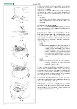
2.3.2-1
2.3.2-2
2.3.2-3
P
N Q
M
L
R
S
monty 3550
2.3.2 Installing the Kit: EAA0304G80A - RAPID
CHANGE-OVER KIT FOR TOOL WITH +4”
EXTENSION
WARNING
BEFORE INSTALLATION, DISCONNECT THE
TIRE CHANGER FROM THE ELECTRICITY AND
COMPRESSED AIR SUPPLIES.
Preliminary operations
See
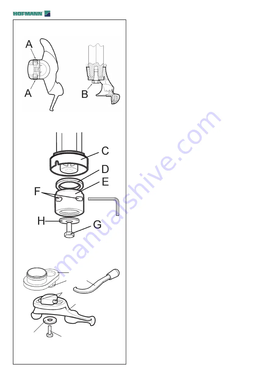
Figure 2.3.2-1
1) Remove the two screws (
A
) from the tool fi tted on the
tire changer.
2) Unscrew and remove the fi xing screw (
B
) underneath
the tool.
3) If the tire changer has a mechanical lever for locking
the hexagonal rod, operate the lever to clamp the rod.
Memorise the position of the tool, then remove it from
the hexagonal rod.
N.B
.: The hexagonal rod will have to be held back by hand
to prevent the vertical spring from pushing it out upwards.
Installing the Kit
See
Figure 2.3.2-2
4) Insert the threaded ring nut (
C
), the washer 41x53x2
(
D
) and place the connection bush (
E
) on the hexagonal
rod, positioned so that the holes for the adjuster screws
are facing upward and in line with the holes in the rod.
5) Screw in the screw 10x20 (
G
) by hand, without
tightening, also fi tting the washer 10x32 (
H
).
6) Screw in the two screws (
F
) supplied in the kit by the
same amount, without tightening, so that the bush remains
centred.
7) Tighten the screws (
F
) fully, tightening them by small
amounts in turn, then to conclude tighten the screw
underneath (
G
).
Installing the tool supplied in the Kit
See
Figure 2.3.2-3
8) Fit the tool supplied in the Kit (
L
) on the snap connection
for the extension, positioned so that the adjuster screws
(
M
) are in line with the seats (
N
) on the hub of the
connection.
9) Screw in the screws (
M
) on the tool by the same amount,
without tightening fully.
10) Screw in the screw 10x30 (
S
) with the washer 10x38
(
R
) by hand, without tightening fully.
11) Fit the assembly formed as described onto the bush
previously fi tted. Tighten the ring nut with the wrench
supplied in the kit (
Q
).
N.B.
: Place the tool in the same position as the original
removed from the tire changer.

