monty 4400
Betriebsanleitung Operator’s Manual Notice d’ utilisation
Modéle :
monty 4400
_D _GB _F - Release D
HOFMANN behält sich das Recht zu Änderungen ohne Vorankündigung vor _ HOFMANN reserves the right of modification without notice _ Document non contractuel
35
4.0 CONTROLS
Before operating the machine ensure that you
have well understood the operation and function
of all the controls.
1.
To turn the machine on, rotate the ON/OFF
switch to position 1 and press the reset button:
the pump motor starts turning and remains in
operation until the machine is turned off. The
power required is minimum when the hydraulic
cylinders are not in use.
NOTE:
IT IS SUGGESTED TO TURN THE MACHINE OFF AFTER
EVERY MOUNTING OR DEMOUNTING OPERATION, IF
THE TIME BEFORE THE NEXT OPERATION IS LONGER
THAN 5 MINUTES.
2.
Press the chuck rotation pedal to the right: the
chuck rotates clockwise. Press the other pedal:
the chuck rotates counter clockwise.
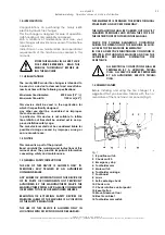
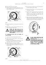
3.
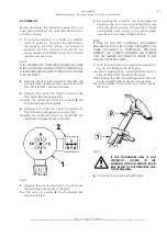
Operate the control (#1 Fig.13) to position
A
:
the chuck arm moves upwards.
Operate the control (#1 Fig.13) to position
B
: the
chuck arm moves downwards.
4.
Operate the control (#1 Fig.13) to position
C
:
the toolholder carriage moves to the right.
Operate the control (#1 Fig.13) to position
D
: the
toolholder carriage moves to the left.
758
Fig.13
5.
Operate the control (#2 Fig.13) to position
A
:
the toolholder arm moves to the right.
Turn the swich to position
B
: the toolholder arm
moves to the left.
6.
By operating the controls in one of the diagonal
positions, the two adjacent movements are
achieved simultaneously. This operation affords
considerable time saving in the intermediate
operations, but requires a little practice.
NOTE:
IF ONE OF THE TWO HYDRAULIC MOVEMENTS
REACHES THE END OF ITS COURSE, THE SPEED OF THE
OTHER MOVEMENT IS APPRECIABLY REDUCED:
INTERRUPT THE CONTROL ENGAGED AND OPERATE
ONLY THE DESIRED MOVEMENT IN ORDER TO GET
NORMAL OPERATING SPEED.
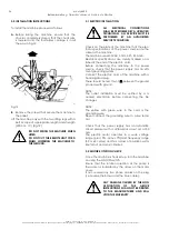
7.
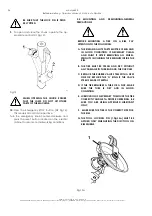
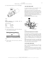
To lift the toolholder arm, depress the pedal (#1
Fig. 14) and hold handle (#2 Fig.14).
The arm is balanced by a spring-loaded mecha-
nism and the effort required is minimum.
When locking the arm into working position be sure
to use enough force to ensure a proper lock.
The heavy metal construction can easily absorb
the force.
400
Fig.14
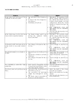
IF THE TOOLHOLDER ARM IS NOT
CORRECTLY
LOCKED
IN
THE
WORKING POSITION SERIOUS INJURI
MAY RESULT TO THE OPERATOR AND
TO THE MACHINE.
8.
To turn the tool remove pin (#2 Fig.14).

