background image

monty 4400


Betriebsanleitung   Operator’s Manual   Notice d’ utilisation


Modéle :  

monty 4400

_D _GB _F - Release D  

HOFMANN behält sich das Recht zu Änderungen ohne Vorankündigung vor _ HOFMANN reserves the right of modification without notice _ Document non contractuel


38

5.2 DEMOUNTING TUBELESS TRUCK TIRES 
(UP TO 13” WIDE) 

 
The  tubeless  truck  tires  are  mounted  on  drop-
center  rims  with  a  conical  base.  It  is  possible  to 
demount  these  tires  simply  by  pressure,  with  a 
proper lubrication (Fig.18). 


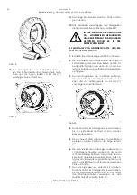
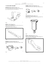
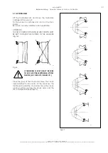
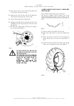
                                                      297


Fig.18 
 

1.


Remove all wheel-weights from the rim.  

Remove the valve stem or core and deflate the  

tire. 


2.


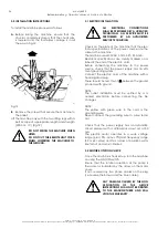
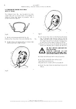
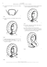
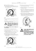
Position the bead breaker disc or tubeless roller 
(option) as shown in Fig.19, Fig.20. 


578 

Fig.19 


579 

Fig.20 
 

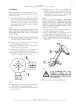
3.


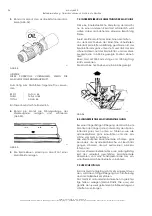
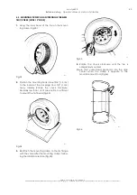
Lift or lower the chuck so that the bead breaker 
disc  or  tubeless  roller  remains  close  to  the  rim 
edge. Turn the chuck counter-clockwise and at 
the same time shift the toolholder carriage step-
by-step toward the inside to demount the tire. 

Continue to turn the chuck and lubricate the bead 

and the rim liberally with an approved lubricant. 


USE  ONLY  SPECIFIC  LUBRICANTS  FOR 
TIRES AND WHEELS. 
APPROVED  LUBRICANTS  DO  NOT 
CONTAIN  WATER,  PETROLEUM  PROD-
UCTS/HYDROCARBONS OR SILICONE.  


4.


Raise the toolholder arm to the rest position.  


5.


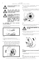
Move the toolholder arm all the way in. 

Lower the arm and secure.  
Bring the tool in contact with the inner bead. 
 

6.


Break  the  inner  bead  as  described  in  point  #3 
above. 


Summary of Contents for monty 4400

Page 1: ...monty 4400 Electric Hydraulic Tire Changer Démonte Pneus Électro Hydraulique Elektrohydraulische Reifenmontiermaschine Operation manual Manuel de l opérateur Betriebsanleitung ...

Page 2: ...eliŠi nin VII ekinin A harfinde belirtilen teknik dosyay haz rlamaya yetkilidir HUN A szakiIrodaIrodavezetŒjefeljogosította œŸ œE irányelvArészénekVII ellékletébenmeghatározott m szakidokumentációösszeállítására RUS Ž Ž VII A œŸ œCE ITA Direttore Operativo SPA Director Operativo POR Director Operacional ENG Operations anager FRA Directeur Opérationnel DEU Betriebsleiter ALB Drejtori Operativ BUL C...

Page 3: ...der SP Содержится в SP DOCUMENTATION SUPPLIED DOCUMENTATION FOURNIE DOCUMENTACIÓN SUMINISTRADA GELIEFERTE DOKUMENTATION DOCUMENTAÇÃO FORNECIDA DOCUMENTAÇÃO FORNECIDA ДОКУМЕНТАЦИИ ПОСТАВЛЯЕМОЙ date of first publication date de la première édition Datum der Erstveröffentlichung data di prima pubblicazione fecha de la primera publicación data da primeira publicação дата первой публикации ENG NOTES REG...

Page 4: ...EN BIS 13 QUERSCHNITT Seite 17 5 4 DEMONTAGE VON LKW SCHLAUCHLOSREIFEN ÜBER 13 DUPLEX SUPERSINGLE BREITE Seite 19 5 5 MONTAGE VON LKW SCHLAUCHLOSREIFEN ÜBER 13 DUPLEX SUPERSINGLE BREITE Seite 20 5 6 DEMONTAGE VON REIFEN AUF SPRENGRINGFELGEN Seite 21 5 7 MONTAGE VON REIFEN AUF SPRENGRINGFELGEN Seite 22 5 8 DEMONTAGE VON LANDWIRTSCHAFTS UND EM RÄDERN AUF TIEFBETIFELGEN Seite 22 5 9 MONTAGE VON LANDW...

Page 5: ...ES DE SÉCURITÉ Page 52 1 4 TERMINOLOGIE Page 52 1 5 CARACTÉRISTIQUES TECHNIQUES Page 53 1 6 DIMENSIONS DE LA MACHINE Page 53 1 7 ACCESSOIRES D ORIGINE Page 53 1 8 ACCESSOIRES EN OPTION Page 54 1 9 PRÉCAUTIONS GÉNÉRALES Page 55 1 10 DISPOSITIFS DE SÉCURITÉ Page 55 2 0 TRANSPORT Page 56 2 1 DÉBALLAGE Page 56 2 2 LIEU D INSTALLATION Page 56 3 0 MONTAGE ET MISE EN OEUVRE Page 57 3 1 BRANCHEMENT ÉLECTR...

Page 6: ...Ge brauch nicht verantwortlich gemacht werden 1 2 ALLGEMEINES Die vorliegende Betriebsanleitung ist Bestandteil des Produktes Lesen Sie die Anweisungen und Warnungen in der vorliegenden Betriebsanleitung genau durch da sie wichtige Hinweise für den sicheren Einsatz und die Wartung dieses Geräts vermitteln 1 3 ALLGEMEINE SICHERHEITSVORSCHRIFTEN DAS GERÄT DARF NUR VON PERSONAL BEDIENT WERDEN DAS DAF...

Page 7: ...äger 1 5 TECHNISCHE DATEN Elektrohydraulische Reifenmontiermaschine für LKW Traktor und EM Reifen mit und ohne Schlauch Maschinengewicht mit Serienzubehör 945 kg 2079 Ibs Elektrischer Anschluß 400 VAC 3 50 60 Hz 9 5 A Pumpemmotorleistung 1 5 kW 2 5 HP Spannfuttermotorleistung 1 5 2 2 kW 2 3 HP Spannvorrichtung 14 32 Max Reifendurchmesser 2300 mm 90 1 2 Max Reifenbreite 1100 mm 43 Max Drehmoment am...

Page 8: ...Kap 5 3 564 Abb 5 4007611 Montageklemme für EM Reifen Abb 6 Erleichtert das Reifenabdrücken von mehrteiligen Felgenringen Zur Verwendungsweise siehe Kap 5 6 396 Abb 6 4008257 Plastikschutz für Leichtmetallfelgen Abb 7 Geeignet für Felgen mit 220 und 280 mm Mitten loch 394 Abb 7 4008264 Plastikschutz für Leichtmetallfelgen Abb 8 Geeignet für Felgen mit 280 mm Mittenloch 667 Abb 8 EAA0373G89A Rolle ...

Page 9: ...NDERE LOSE ACCESSOIRES GETRAGEN WERDEN AUCH LANGE HAARE SIND GEFÄHRLICH UND DESHALB ENTSPRECHEND ZU SCHÜTZEN DER BEDIENER MUSS EINE ANGEMESSENE SICHERHEITSAUSRÜSTUNG TRAGEN WIE HANDSCHUHE SICHERHEITSSCHUHE UND SCHUTZBRILLE F ELEKTRISCHE KABEL MÜSSEN IN GUTEM ZUSTAND GEHALTEN WERDEN G DER RADSCHUTZ UND DIE ANDEREN SICHERHEITSVORRICHTUNGEN MÜSSEN IMMER FUNKTIONSBEREIT GEHALTEN WERDEN H DAS ARBEITSUM...

Page 10: ... KRATZER UND SCHÜRFUNGEN DURCH DEN KON TAKT MIT DEM VERPACKUNGSMA TERIAL ZU VERMEIDEN 2 2 AUFSTELLUNGSORT Die Maschine an einem trockenen und überdach ten möglichst geschlossenen Ort aufstellen Für die Aufstellung der Maschine wird eine Nutzflä che von 500x500cm 16 5 x16 5 Abb 11 757 Abb 11 Sicherstellen daß der Bediener von der Bedienposi tion aus das gesamte Gerät und das Umfeld einse hen kann D...

Page 11: ...stungsdaten aus gelegt 400 VAC 50 Hz 3 Ph 9 5 A Die elektrischen Daten sind deutlich auf einem An hänger aufgeführt der am Ende des Anschlußka bels befestigt ist Vor dem Anschluß der Maschine den Zustand der Leitungen und das Vorhandensein einer leistungs starken Erdung überprüfen An das Maschinenkabel einen zugelassenen Ste cker anschliessen HINWEIS Bevor das Gerät angeschlossen wird muß eine Ele...

Page 12: ...gen der Spannfutterrahmen fährt nach rechts Den Knüppel 1 Abb 13 in Position D bewe gen der Werkzeugschlitten fährt nach links 758 Abb 13 5 Den Steuerknüppel 2 Abb 13 in Position A bewegen der Werkzeugträger fährt nach rechts Den Knüppel in Position B bewegen der Werk zeugträger fährt nach links 6 Wird der Steuerknüppel in eine der Diagonal stellungen gebracht werden die beiden anlie genden Bewegu...

Page 13: ...ICHTSMASSNAHMEN BEI REIFEN MONTAGE UND DEMONTAGE VOR DER REIFENMONTAGE FOLGENDE VOR SICHTSMASSREGELN BEACHTEN A DIE FELGE MUSS SAUBER UND IN GUTEM ZUSTAND SEIN FALLS NÖTIG DIE FELGE REINIGEN UND EINPINSELN NACHDEM ALLE ALTEN AUSGLEICHSGEWICHTE AUCH DIE KLEBEGEWICHTE AUF DER FELGENINNEN SEITE ENTFERNT WURDEN B DER REIFEN MUSS SAUBER UND TROCKEN SEIN WEDER REIFENWULST NOCH REIFENMANTEL DÜRFEN BESCHÄ...

Page 14: ... entsprechenden Plastik schutz ausstatten WICHTIGER HINWEIS FELGEN MIT TIEFBETT SIND SO ZU SPANNEN DASS DAS TIEFFBET ZUR MASCHINENAUSSENSEITE ZEIGT Abb 16 402 Abb 16 RÄDER MIT MEHRALS 1 5M DURCH MESSER ODER 200 Kg GEWICHT DÜR FEN NUR MIT HILFSMITTELN TRANS PORTIERT WERDEN FÜR DIESE ARBEI TEN SIND 2 PERSONEN ERFORDER LICH Die Spannklauen der Spannvorrichtung schließen und das Spannfutter ungefähr k...

Page 15: ...ückscheibe oder die Schlauchlosrei fenrolle auf Anfrage wie in Abb 19 und in Abb 20 gezeigt positionieren 578 Abb 19 579 Abb 20 3 Das Spannfutter soweit nach oben unten fah ren daß die Abdrückscheibe oder die Schlauchlosrolle am Felgenhorn anliegen Das Spannfutter gegen den Uhrzeigersinn drehen und gleichzeitig den Werkzeugschlitten in kur zen Abständen nach außen fahren um den Reifen abzudrücken ...

Page 16: ...und dabei den Werkzeugschlitten nach außen fah ren bis die beiden Wülste aus der Felge geba ben sind Abb 21 und Abb 22 580 Abb 21 581 Fig 22 SICHERSTELLEN DASS DER ÄUSSERE WULST GENAU GEGENÜBER VOM WERKZEUG INS TIEFBETT RUTSCHT ANDERN FALLS KANN DIE DEMON TAGE NICHT ERFOLGREICH DURCH GEFÜHRT WERDEN 410 8 Sich gegenüber vom Reifen aufstellen und die sen in der Endphase der Demontage mit bei den Hän...

Page 17: ...gig schmieren Die Montage klemme am Felgenaußenrand anbringen Abb 24 wobei das Ventil in 11 Uhr Position und die Klemme in 12 Uhr Position stehen muß 412 Abb 24 Handelt es sich um eine ALU Felge könnte die Form des Felgenhorns das Anbringen einer Standardmontageklemme unmöglich machen In diesem Fall ist eine Spezialklemme für Alufel gen zu verwenden Sonderzubehör Diese Klemme kann dann wie in Abb ...

Page 18: ...befindet sich dabei in 11 Uhr Stellung 416 Abb 28 NIE DIE HÄNDE VERWENDEN UM DEN REIFEN AUF DER FELGE ZU HALTEN 4 Das Spannfutter im Uhrzeigersinn soweit drehen bis der Reifen vollständig montiert ist Abb 29 417 Abb 29 SICHERSTELLEN DASS DER ÄUSSERE WULST SICH INS TIEFBETT SCHIEBT WENN SICH DIE MONTAGEKLEMME GENAU GEGENÜBER VOM WERKZEUG BEFINDET 423 DAS SPANNFUTTER ANHALTEN BEVOR EINE VOLLSTÄNDIGE...

Page 19: ... 5 2 1 bis 5 2 6 beschrieben 2 Bei diesem Reifentyp ist eine gleichzeitige De montage wie unter 5 2 7 beschrieben nicht möglich Den Montagehaken zwischen Wulst und Felge einhängen 3 Den Hubarm heben um das Werkzeug vom Felgenhorn freizustellen 2 3 cm Das Werkzeug nach außen bewegen sodaß das lange Mon tiereisen angesetzt werden kann Abb 30 418 Abb 30 4 Das Spannfutter gegen den Uhrzeigersinn dre h...

Page 20: ... Abb 33 2 Den Montagehaken so einsetzen da er innen in ca 1 5 cm 1 2 Abstand zum Felgenrand steht und nach oben ca 1 cm 1 2 Abstand hat Die Spannvorrichtung im Uhrzeigersinn drehen Normalerweise genügt 1 4 Drehung um den ersten Wulst zu montieren Abb 34 586 Abb 34 3 Die Montierklemme am Felgenrand so befesti gen daß sich das Ventil in bezug auf die Dreh richtung hinter der Klemme befindet Abb 35 4...

Page 21: ...n Ausgleichsgewichte von der Felge entfernen Das Ventil herausnehmen und die Luft aus dem Reifen lassen 2 Die Abdrückscheibe am Felgenrand ansetzen Abb 38 Wenn der Sprengring am Reifen ver klebt ist bei EM Reifen ist es zum Abdrücken nötig ihn mit der Spezialklemme 4007611 auf Anfrage an die Felge zu binden 426 Abb 38 3 Das Spannfutter gegen den Uhrzeigersinn dre hen und das Abdrücken vornehmen wi...

Page 22: ...e des Sprengrings in die Rille einlegen und die Montage mit Hilfe der Abdrückscheibe zu Ende führen In der Anfangsphase das Sprengringende mit ei nem Hebel in der Rille halten Abb 41 588 Abb 41 DEN REIFEN NICHT AUF DER MASCHINE AUFPUMPEN DIE REIFENMONTIERMASCHINE IST KEINE REIFENFÜLLVORRICHTUNG DAS REIFENFÜLLEN DARF NUR IN EINEM VORSCHRIFTSMÄSSIGEN SICHERHEITSKÄFIG DURCHGE FÜHRT WERDEN 5 8 DEMONTA...

Page 23: ...ulst und Felge einhängen Abb 45 590 Abb 45 6 Den Hubarm heben um das Werkzeug vom Felgenhorn freizustellen 2 3 cm 1 Das Werk zeug nach außen bewegen sodaß das lange Montiereisen angesetzt werden kann Abb 46 591 Abb 46 7 Das Spannfutter gegen den Uhrzeigersinn dre hen bis der äußere Wulst vollkommen demon tiert ist Abb 47 592 Abb 47 8 Ist ein Schlauch vorhanden das Ventil in die Felge drücken 9 Den...

Page 24: ...ntierklemme am Außenrand der Felge in 9 Uhr Stellung ansetzen Den Reifen auf die Ar beitsplattform rollen und ebenfalls an der be reits am Felgenhorn befestigten Montierklemme einhängen 3 Den Montagehaken wie in Abb 50 positionie ren Die Spitze des Montagehakens muß nach oben und von außen jeweils ca 2 3 cm 1 vom Felgenhorn entfernt sein 595 Abb 50 4 Das Spannfutter im Uhrzeigersinn soweit drehen ...

Page 25: ...EINES BESONDERS SCHWEREN RADES MUSS EIN ANGEMESSENES HEBEMITTEL VERWENDET WERDEN UM DAS RAD IN DER VERTIKALEN POSITION ZU HALTEN HUBKARREN FLASCHENZUG ETC 3 Das Rad in der vertikalen Position halten und anschließend den Befestigungsring lockern 4 Das Befestigungswerkzeug beseitigen anschließend parallel nach außen verschieben um das bewegliche Trittbrett von der Spindel zu entfernen 5 Das Rad abne...

Page 26: ...nfutter vollständig geschlossen ist der Spannfutterarm ganz unten steht und daß der Ma schinenrahmen auf der Spannfutter und der Werk zeugseite die in Abb 56 gezeigte Position einneh men Einen Gurt mit 3000 mm Länge und 1000 kg Trag kraft verwenden Die Maschine hochheben wie in Abb 56 gezeigt 397 Abb 56 8 0 LÄNGERFRISTIGE MASCHINENSTILLEGUNG Bei einer längerfristigen Stillegung der Maschine 6 Mona...

Page 27: ...kasten öffnen und den magnetothermischen Schutz schalter wieder in den Ausgangs zustand versetzen DIESE ARBEIT DARF NUR VON ELEKTROFACHKRÄFTEN VORGENOMMEN WERDEN Der magnetothermische Schutz schalter am Pumpenmotor schal tet leicht ab Zu niedrige Versorgungsspan nung Netzspannung überprüfen DIESE ARBEIT DARF NUR VON ELEKTROFACHKRÄFTEN VORGENOMMEN WERDEN Der Automatikschalter schlägt leicht durch M...

Page 28: ...perator s Manual Notice d utilisation Modéle monty 4400_D _GB _F Release D HOFMANN behält sich das Recht zu Änderungen ohne Vorankündigung vor _ HOFMANN reserves the right of modification without notice _ Document non contractuel 28 ...

Page 29: ...structions of this manual since they provide important information concerning safety and maintenance 1 3 GENERAL SAFETY INSTRUCTIONS THE USE OF THIS DEVICE IS ALLOWED ONLY TO PERSONNEL DULY TRAINED BY AN AUTHORIZED HOFMANN DEALER ANY MISUSE OR MODIFICATION OF THIS DEVICE OR OF ITS PARTS OR COMPONENTS NOT PREVIOUSLY AUTHORIZED BY THE MANUFACTURER WAIVE THE MANUFACTURER FROM ANY DAMAGE CONSEQUENT OR...

Page 30: ...s 400VAC 3ph 50 60Hz 9 5A Hydraulic motor power 1 5 kW 2 HP Chuck rotation motor power 1 5 2 2 kW 2 3 HP Chuck capacity 14 56 Max tire diameter 2300 mm 90 1 2 Max tire width 1100 mm 43 Max chuck torque 3100 Nm 2268 ftxlbs Clamping power 60kN Chuck rotation speed 4 8 rpm Acoustic pressure 70dBA 1 6 DIMENSIONS OF THE MACHINE 520 Fig 2 1 7 STANDARD ACCESSORIES 0001418 Shore tire tool 4004461 Long tir...

Page 31: ...s in section 5 3 564 Fig 5 4007611 O T R Clamp Fig 6 Useful when breaking the bead from the rim on multi piece wheels O T R Instructions for use is in section 5 6 396 Fig 6 4008257 Protectors for alloy rims Fig 7 Suitable for rims with a center hole of 220 and 280 mm 394 Fig 7 4008264 Protectors for alloy rims Fig 8 Suitable for rims with a center hole of 280 mm only 667 Fig 8 EAA0373G89A Tubeless...

Page 32: ...REPAIRS ARE ACCOMPLISHED THE MACHINE MUST BE DISCONNECTED FROM THE ELECTRIC SUPPLY E NEVER WEAR TIES CHAINS OR OTHER LOOSE ARTICLES WHEN USING MAINTAINING OR REPAIRING THE MACHINE LONG HAIR IS ALSO DANGEROUS AND SHOULD BE KEPT UNDER A HAT THE USER MUST WEAR PROPER SAFETY ATTIRE I E GLOVES SAFETY SHOES AND GLASSES F MAINTAIN ALL ELECTRIC CORDS IN GOOD REPAIR G KEEP SAFETY FEATURES IN PLACE AND IN W...

Page 33: ...NCRATING THE MACHINE TO PREVENT SCRATCHES OR ABRA SIONS DUE TO THE CONTACT WITH PACKING MATERIALS 2 2 INSTALLATION AREA Install the machine in a covered and dry area The installation of the machine requires a free space of at least cm 500x500 16 5 x16 5 Fig 11 757 Fig 11 Make sure that from the operating position the user can see all of the machine and the surrounding area The operator shall forbi...

Page 34: ...s 400VAC 50 Hz 3Ph 9 5 Amp Electrical specifications are clearly marked on a label at the end of the electric cord Before connecting the machine to the power source check that the power supply has an effi cient grounding system Connect the electric cord of the machine with a homologated plug There should be less than 1 Ω between the ground pin and earth ground NOTE The outlet installation must be ...

Page 35: ... the control 1 Fig 13 to position C the toolholder carriage moves to the right Operate the control 1 Fig 13 to position D the toolholder carriage moves to the left 758 Fig 13 5 Operate the control 2 Fig 13 to position A the toolholder arm moves to the right Turn the swich to position B the toolholder arm moves to the left 6 By operating the controls in one of the diagonal positions the two adjacen...

Page 36: ...sume normal working conditions 5 0 MOUNTING AND DEMOUNTING GENERAL PRECAUTIONS BEFORE MOUNTING A TIRE ON A RIM PAY ATTENTION TO THE FOLLOWING A THE RIM AND ALL ITS PARTS MUST BE CLEAN AND IN GOOD CONDITION IF NECESSARY CLEAN AND PAINT IT AFTER REMOVING ALL WHEEL WEIGHTS INCLUDING TAPE WEIGHTS INSIDE THE RIM B THE TIRE MUST BE CLEAN AND DRY WITHOUT ANY DAMAGE TO THE BEAD AND THE CARCASS C REPLACE T...

Page 37: ...he wheel in vertically and roll it on the foot board Be sure to use alloy adapters when applicable ATTENTION THE DROP CENTER OF THE RIM WHEN IT EXISTS MUST BE KEPT TOWARDS THE OUTSIDE OF THE MACHINE Fig 16 402 Fig 16 IF THE WHEEL IS VERY HEAVY BE SURE TO USE A SUITABLE EXTERNAL LIFTING DEVICE I E FORK LIFT CRANE ETC Close the jaws of the chuck and move the chuck approximately to the center of the ...

Page 38: ...ition the bead breaker disc or tubeless roller option as shown in Fig 19 Fig 20 578 Fig 19 579 Fig 20 3 Lift or lower the chuck so that the bead breaker disc or tubeless roller remains close to the rim edge Turn the chuck counter clockwise and at the same time shift the toolholder carriage step by step toward the inside to demount the tire Continue to turn the chuck and lubricate the bead and the ...

Page 39: ...tinue rotating the chuck moving toolholder carriage towards the outside until the beads are demounted from the rim Fig 21 and Fig 22 580 Fig 21 581 Fig 22 ENSURE THAT THE OUTER BEAD SLIDES INTO THE DROP CENTER OPPOSITE TO THE TOOL OTHERWISE THE DE MOUNTING OPERATION IS IMPOSSI BLE 410 8 Move to the front of the tire and hold it with both hands in the last part of demounting op eration to prevent t...

Page 40: ...the entire inner surface of the rim and the tire beads Attach the mounting clamp Fig 24 to the outer rim flange with the valve at 11 o clock and the clamp at 12 o clock 412 Fig 24 If the rim is made of a ligth alloy the rim shape may not allow the standard mounting clamp to be attached In such a case use the light alloy mounting clamp option The clamp can be used as shown in Fig 25 or 26 583 Fig 2...

Page 41: ...s at 11 o clock approximate ly 416 Fig 28 NEVER USE HAND PRESSURE TO HOLD THE TIRE ONTO THE RIM 4 Turn the chuck clockwise until the tire is com pletely mounted Fig 29 417 Fig 29 ENSURE THAT THE OUTER BEAD DESCENDS INTO THE DROP CENTER WHEN THE CLAMP IS OPPOSITE TO THE TOOL 423 STOP THE CHUCK BEFORE ONE COMPLETE TURN IS MADE TO AVOID SERIOUS DAMAGE TO THE MOUNTING CLAMP AND TO THE RIM DO NOT INFLA...

Page 42: ...ed in 5 2 1 5 2 6 2 For this type of tire it is not possible to demount both beads at the same time as described in 5 2 7 Engage the hook of the mount demount tool be tween the bead and the rim 3 Lift the chuck arm enough to clear the hook 2 3 cm 1 1 1 2 from the rim flange Move the mount demount tool towards the outside This will allow you to place the long bar in between the bead and the rim fla...

Page 43: ...ing clamp Fig 33 420 Fig 33 2 Position the mounting hook about 3 4 1 5 cm to the inside of the rim edge and 1 2 1 cm away radially Rotate the chuck clockwise Normally less than 1 4 of a revolution is sufficient to mount the first bead Fig 34 586 Fig 34 3 Reattach the mounting clamp to the rim flange with the valve after the mounting clamp follow ing the rotation direction Fig 35 416 Fig 35 4 Rotat...

Page 44: ...eights from the rim Remove the valve stem or core and deflate the tire 2 Position the tool close to the rim edge Fig 38 When the lock ring is stuck to the bead on the O T R tires to make it to break the bead it is necessary to hold it to the rim with the appro priate clamp 4007611 on request 426 Fig 38 3 Turn the chuck counter clockwise and the break bead as described in 5 2 1 5 2 3 Do not lubrica...

Page 45: ... a bar Fig 41 588 Fig 41 DO NOT INFLATE THE TIRE ON THE MACHINE THIS MACHINE IS NOT AN INFLATION DEVICE FOR INFLATION PLACE THE WHEEL IN AN APPROVED INFLATION RESTRAINT DEVICE IN THE UNITED STATES OF AMERICA CONSULT O S H A REGULATIONS CONCERNING THE PROPER SERVICING OF TRUCK WHEELS AND RIMS 5 8 DEMOUNTING TRACTOR AND O T R WHEELS WITH ONE PIECE RIMS These wheels may be tube type or tubeless The r...

Page 46: ...ead and rim Fig 45 590 Fig 45 6 Lift the chuck arm to move the hook tool away from the rim edge 1 or 2 3 cm Move the tool towards the outside to apply the long tire bar Fig 46 591 Fig 46 7 Turn the chuck counter clockwise until the outer bead is completely demounted Fig 47 592 Fig 47 8 If the tire is tube type push the valve stem to wards the inside of the rim 9 Lift the toolholder arm to the rest...

Page 47: ...ck Roll the tire onto the footboard and hang it on the mounting clamp attached to the rim edge 3 Place the hook tool as shown in Fig 50 The edge of the hook should be about 2 3 cm 1 away radially from the rim edge and 2 3 cm 1 to the outside 595 Fig 50 4 Turn the chuck clockwise until the first bead is mounted Remove the clamp 5 Place the tube if any in the tire and secure the valve stem to the ri...

Page 48: ...KLIFT TRUCK HOIST ETC 3 Hold the wheel in the vertical position and then loosen the locking ring nut 4 Remove the fixing tool and then move outwards to move the mobile board away from the spindle 5 Remove the wheel by rolling or lifting from the board with the workshop lift 6 0 MAINTENANCE BEFORE STARTING ANY MAINTE NANCE OPERATION ENSURE THAT NO WHEEL IS MOUNTED ON THE CHUCK AND THAT THE MACHINE ...

Page 49: ...losed the chuck arm lowered and that the arm beam support and carriage beam support are in the position indicated in Fig 56 Use belts of a length of mm 3000 10 and capaci ty of kg 1000 2200 lbs Hold the machine as depicted in Fig 56 397 Fig 56 8 0 PUTTING THE MACHINE OUT OF SERVICE If the machine is to be idle for a long period of time 6 months or more it is necessary to close the chuck arm retrac...

Page 50: ...ther mal safety switch THIS OPERATION CAN BE PERFORMED ONLY BY QUALIFIED PERSONNEL The thermal switch that protects the pump motor is very easily activat ed The voltage of the electric line is too low Check voltage on electric sup ply THIS OPERATION CAN BE PERFORMED ONLY BY QUALIFIED PERSONNEL The circuit breaker is very easily ac tivated The machine is not stable on the floor The electric cabinet...

Page 51: ...perator s Manual Notice d utilisation Modéle monty 4400_D _GB _F Release D HOFMANN behält sich das Recht zu Änderungen ohne Vorankündigung vor _ HOFMANN reserves the right of modification without notice _ Document non contractuel 51 ...

Page 52: ... Ce manuel fait partie intégrante du produit Lire attentivement les instructions et les notices ex plicatives contenues dans ce manuel puisqu elles donnent des indications importantes pour ce qui concerne la sécurité d emploi et l entretien 1 3 RÈGLES GÉNÉRALES DE SÉCURITÉ L EMPLOI DE L APPAREIL EST PERMIS SEULEMENT AU PERSONNEL OPPORTUNÉMENT FORMÉ PAR LE DISTRIBUTEUR AUTORISÉ HOFMANN TOUT ET N IM...

Page 53: ...QUES TECHNIQUES Démonte pneus électro hydraulique pour pneus de camion tubeless sans chambre à air Poids avec accessoires en dotation 945kg 2079lbs Caractéristiques électriques 400VAC3 50 0Hz 9 5A Puissance moteur pompe 5 kW 2 HP Puissance moteur arbre 1 5 2 2 kW 2 3 HP Blocage jante 14 56 Diamètre maxi Pneu 2300 mm 90 1 2 Largeur maxi Pneu 1100 mm 43 Couple maximum à l arbre 3100 Nm 2268 ftxlbs F...

Page 54: ... 5 3 564 Fig 5 4007611 Étau roues de génie civil Fig 6 Facilite le détalonnage du pneu de la jante en plu sieurs parties Les instructions pour l emploi sont décrites au paragraphe 5 6 396 Fig 6 4008257 Protections pour jantes en alliage Fig 7 Indiquées pour jantes avec trou central de 220 et de 280 mm 394 Fig 7 4008264 Protections pour jantes en alliage Fig 8 Indiquées pour jantes avec trou centra...

Page 55: ...UTE DES OPÉRATIONS D EMPLOI D ENTRETIEN OU DE RÉPARATION SUR LA MACHINE LES CHEVEUX LONGS SONT ÉGALEMENT DANGEREUX ILS DOIVENT ÊTRE RASSEMBLÉS SOUS UNE CASQUETTE OU AUTRE L OPÉRATEUR DOIT PORTER DES VÊTEMENTS ADÉQUATS DES GANTS DES CHAUSSURES DE SÉCURITÉ ET DES LUNETTES F LES CÂBLES ÉLECTRIQUES DOIVENT ÊTRE CONSERVÉS EN BON ÉTAT G LE CARTER DE SÉCURITÉ ET LES DISPOSITIFS DE SÉCURITÉ DOIVENT ÊTRE A...

Page 56: ...lon les règles locales en vi gueur PORTER TOUJOURS LES GANTS PENDANT LE DÉBALLAGE POUR ÉVITER DES GRIFFURES OU DES ÉGRATIGNURES DUES AU CONTACT AVEC LE MATÉRIEL DE L EMBALLAGE 2 2 LIEU D INSTALLATION Installer la machine dans un lieu couvert sec et si possible clos L installation de la machine nécessite un espace utile d au moins 500x500 cm 16 5 x16 5 Fig 11 757 Fig 11 S assurer que l opérateur so...

Page 57: ... du réseau La machine nécessite 400VCA 50 60Hz 3Ph 9 5 A Les caractéristiques électriques sont indiquées clai rement sur une étiquette au bout du câble élec trique Avant de procéder au branchement vérifier la condition des conducteurs et la présence d une installation de terre efficace Relier le câble électrique de la machine à une fiche homologuée REMARQUE L installation électrique de distributio...

Page 58: ...evier du manipulateur 1 Fig 13 en position C le chariot porte outil se déplace vers la droite Actionner le levier 1 Fig 13 en position D le chariot porte outil se déplace vers la gauche 758 Fig 13 5 Actionner le levier du manipulateur 2 Fig 13 en position A le bras porte outil se déplace vers la droite Actionner le levier en position B le bras porte outil se déplace vers la gauche 6 En actionnant ...

Page 59: ...males conditions de travail 5 0 MONTAGE ET DÉMONTAGE PNEUS PRÉCAUTIONS GÉNÉRALES AVANT DE MONTER LE PNEU SUR LA JANTE RESPECTER LES INDICATIONS SUIVANTES A LA JANTE DOIT ÊTRE PROPRE ET EN BON ÉTAT SI NÉCESSAIRE LA NETTOYER ET LA PEINDRE APRÈS AVOIR ENLEVÉ TOUTES LES MASSES Y COMPRIS LES MASSES COLLÉES ÉVENTUELLEMENT APPLIQUÉES À L INTÉRIEUR DE LA JANTE B LE PNEU DOIT ÊTRE PROPRE ET SEC ET NI LE TA...

Page 60: ...ancher Si on doit bloquer des jantes en tôle monter les protections prévues sur les griffes IMPORTANT LE CREUX DE LA JANTE S IL EXISTE DOIT TOUJOURS ÊTRE VERS L EXTÉRIEUR DE LA MACHINE Fig 16 402 Fig 16 SI LA ROUE EST PARTICULIÈREMENT LOURDE UTILISER UN OUTIL DE LEVAGE EXTÉRIEUR ADÉQUAT CHARIOT ÉLÉVATEUR PALAN ETC Fermer les griffes du centreur automatique et posi tionner l arbre à peu près sur le...

Page 61: ...tubeless option comme montré sur la Fig 19 et la Fig 20 578 Fig 19 579 Fig 20 3 Soulever ou abaisser l arbre à ce que le disque détalonneur ou le rouleau tubeless soient au bord de la jante Tourner l arbre dans le sens in verse des aiguilles d une montre et simultané ment déplacer le chariot porte outil à de brefs intervalles vers le pneu Continuer à tourner l arbre en graissant abon damment avec ...

Page 62: ... le mandrin en déplaçant le chariot porte outil vers l extérieur jusqu à faire sortir les deux talons de la jante Fig 21 et Fig 22 580 Fig 21 581 Fig 22 VÉRIFIER QUE LE TALON EXTÉRIEUR DESCENDE DANS LE CANAL DE LA JANTE EN POSITION DIAMÉTRALEMENT OPPOSÉE À L OUTIL DANS LE CAS CONTRAIRE LE DÉMONTAGE EST IMPOSSIBLE 410 8 Se placer face au pneu et le retenir des deux mains dans la phase finale du dém...

Page 63: ...damment toute la surface inté rieure de la jante et les talons du pneu Fixer l étau de montage Fig 24 au bord extérieur de la jante avec la valve à 11 heures et l étau à 12 heures 412 Fig 24 Si la jante est en tôle légère la forme du bord pourrait empêcher de fixer l étau standard Dans ce cas utiliser l étau pour jantes en tôle en option L étau peut être fixé comme mon tré sur la fig 25 ou 26 583 ...

Page 64: ...n direction ra diale Fig 28 L étau de montage se trouve à 11 heures 416 Fig 28 NE JAMAIS RETENIR LE PNEU SUR LA JANTE AVEC LES MAINS 4 Tourner l arbre dans le sens des aiguilles d une montre jusqu à ce que le pneu ne soit complè tement monté Fig 29 417 Fig 29 VÉRIFIER QUE LE TALON EXTÉRIEUR DESCENTE DANS LE CANAL LORSQUE L ÉTAU EST DIAMÉTRALEMENT OPPOSÉ À L OUTIL 423 ARRÊTER L ARBRE AVANT D AVOIR ...

Page 65: ...onner le pneu comme décrit en 5 2 1 5 2 6 2 Pour ce type de pneu il est impossible de dé monter les deux talons en même temps comme décrit au 5 2 7 Insérer le crochet de l outil entre le talon et la jante 3 Lever le bras porte arbre de manière à éloigner l outil du bord de la jante 2 3 cm Déplacer l outil vers l extérieur pour pouvoir insérer le levier soulève talons long Fig 30 418 Fig 30 4 Tourn...

Page 66: ...ormalement il suffit d un quart de tour pour monter le premier talon Fig 34 586 Fig 34 3 Fixer l étau de montage sur le bord extérieur de la jante de manière à avoir la soupape après l étau suivant la direction de rotation Fig 35 416 Fig 35 4 Tourner l autocentreur dans le sens des aiguilles d une montre jusqu à ce que le pneu soit com plètement monté Veiller à ce que le talon exté rieur descende ...

Page 67: ...e montre et effectuer le détalonnage sui vant la description des 5 2 1 5 2 3 Ne pas graisser 4 Pour enlever la bague élastique de blocage soulever une extrémité à l aide du levier sou lève talons et y insérer le disque détalonneur comme le montre la Fig 39 587 Fig 39 5 Tourner l autocentreur dans le sens des aiguilles d une montre jusqu à ce que la bague ou l an neau sectionné sorte complètement N...

Page 68: ...e dans son logement et terminer le montage à l aide du disque détalonneur Pendant la phase initiale du montage retenir l extrémité de la bague élastique dans son siège à l aide d un le vier Fig 41 588 Fig 41 NE PAS GONFLER LE PNEU SUR LA MACHINE LA MACHINE N EST PAS UN DISPOSITIF POUR LA GONFLAGE POUR GONFLER LA ROUE LA PLACER DANS UNE CAGE HOMOLOGUÉE 5 8 DÉMONTAGE DES ROUES AGRICOLES ET DE GÉNIE ...

Page 69: ...jante Fig 45 590 Fig 45 6 Lever le bras porte arbre de façon à éloigner l outil du bord de la jante 2 3 cm 1 Dépla cer l outil vers l extérieur de manière à insérer le levier soulève talons long Fig 46 591 Fig 46 7 Tourner l arbre dans le sens inverse aux aiguilles d une montre jusqu à ce que le talon extérieur ne soit complètement sorti Fig 47 592 Fig 47 8 S il y a la chambre à air pousser la sou...

Page 70: ... CIVIL AVEC JANTES À BASE CREUSE 1 Graisser abondamment les talons et la jante 2 Accrocher l étau de montage sur le bord exté rieur de la jante à 9 heures Rouler le pneu sur le plancher et l accrocher à l étau placé sur le bord de la jante 3 Positionner le crochet comme le montre la Fig 50 L extrémité du crochet doit être à une distance de 2 3 cm 1 environ du bord de la jante et de 2 3 cm 1 de l e...

Page 71: ... toucher la rampe REMARQUE SI LA ROUE EST PARTICULIEREMENT LOURDE UTILISER UN MOYEN DE LEVAGE POUR LA MAINTENIR A LA VERTICALE CHARIOT ELEVATEUR PALAN ETC 3 Maintenir la roue en position verticale puis desserrer la bague de fixation 4 Retirer l outil de fixation puis déplacer latéralement vers l extérieur pour éloigner la rampe mobile du mandrin 5 Retirer la roue en la faisant rouler ou en la soul...

Page 72: ...eur soit fermé que le bras porte arbre soit complètement abaissé et que le châssis porte bras et le châssis porte chariot soient dans la posi tion indiquée par la Fig 56 Utiliser un élingage de 3000 mm de long 10 et de 1000kg de capacité de levage 2200 lbs Soulever la machine comme montré sur la Fig 56 397 Fig 56 8 0 MISE DE CÔTÉ Au cas où la machine ne serait pas utilisée pen dant une longue péri...

Page 73: ...FIÉ L interrupteur magnétothermique qui protège le moteur de la pompe se déclenche facilement Tension électrique d alimenta tion de la machine trop basse Contrôler la tension du réseau électrique CETTE OPÉRATION PEUT ÊTRE EFFECTUÉE EXCLUSIVEMENT PAR DU PERSONNEL QUALIFIÉ L interrupteur automatique du cir cuit se déclenche facilement La machine n est pas fixée au sol de manière stable La boîte du s...

Page 74: ...perator s Manual Notice d utilisation Modéle monty 4400_D _GB _F Release D HOFMANN behält sich das Recht zu Änderungen ohne Vorankündigung vor _ HOFMANN reserves the right of modification without notice _ Document non contractuel 74 ...

Page 75: ...perator s Manual Notice d utilisation Modéle monty 4400_D _GB _F Release D HOFMANN behält sich das Recht zu Änderungen ohne Vorankündigung vor _ HOFMANN reserves the right of modification without notice _ Document non contractuel 75 ...

Page 76: ...on contained in this document is subject to change without notice Hofmann makes no warranty with regard to present documentation Hofmann shall not be liable for errors contained herein or for incidental consequential damages in connection with furnishings performance or use of this material Snap on Equipment SrL Manufacturing Facility Via Per Carpi 33 42015 Correggio RE Italy www snapon equipment ...

Reviews:

Related manuals for monty 4400