monty 4400
Betriebsanleitung Operator’s Manual Notice d’ utilisation
Modéle :
monty 4400
_D _GB _F - Release D
HOFMANN behält sich das Recht zu Änderungen ohne Vorankündigung vor _ HOFMANN reserves the right of modification without notice _ Document non contractuel
47
10.
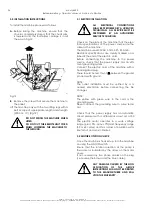
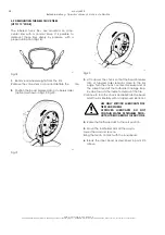
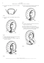
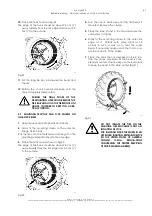
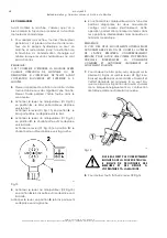
Place the hook tool as in Fig.49.
The edge of the hook should be about 2-3 cm (1")
away radially from the rim edge and about 2-3
cm (1") to the outside.
594
Fig.49
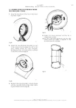
11.
Put the long tire bar in between the bead and
the rim.
12.
Rotate the chuck counter-clockwise until the
tire is completely demounted.
DURING THE FINAL PHASE OF THE
DEMOUNTING OPERATION REMOVE THE
TIRE BAR AND HOLD THE TIRE WITH BOTH
HANDS, IN ORDER TO KEEP IT IN A VER-
TICAL POSITION.
5.9 MOUNTING TRACTOR AND O.T.R. WHEELS ON
ONE-PIECE RIMS
1.
Liberally lubricate both beads and the rim.
2.
Firmly fit the mounting clamp to the outer rim
flange at 9 o'clock.
Roll the tire onto the footboard and hang it on the
mounting clamp attached to the rim edge.
3.
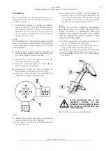
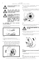
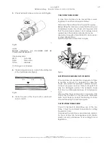
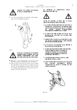
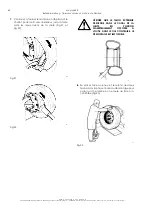
Place the hook tool as shown in Fig.50.
The edge of the hook should be about 2-3 cm (1")
away radially from the rim edge and 2-3 cm (1")
to the outside.
595
Fig.50
4.
Turn the chuck clockwise until the first bead is
mounted. Remove the clamp.
5.
Place the tube (if any) in the tire and secure the
valve stem to the rim.
6.
Firmly fit the mounting clamp to the outer rim
edge at 11 o'clock with valve stem at 10
o'clock in such a way as to hold the outer
bead. If necessary make use of the tool to cre-
ate the space to fit the clamp.
7.
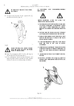
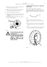
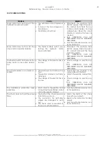
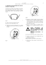
Place the hook tool as described in 5.5.2. Ro-
tate the chuck clockwise till the bead is com-
pletely mounted. If necessary, use the bead bar
to keep the bead in the drop center (Fig.51).
596
Fig.51
DO NOT INFLATE THE TIRE ON THE
MACHINE. THIS MACHINE IS NOT AN
INFLATION DEVICE.
FOR INFLATION PLACE THE WHEEL IN AN
APPROVED INFLATION RESTRAINT DEVICE
(IN THE UNITED STATES OF AMERICA
CONSULT
O.S.H.A.
REGULA-TIONS
CONCERNING THE PROPER SERVICING
OF TRUCK, WHEELS AND RIMS).


