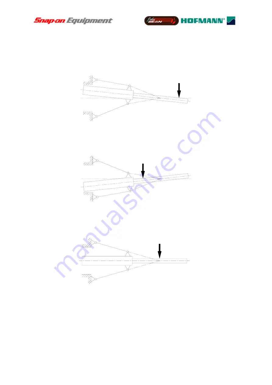
vibration. If forces are applied left of the node of vibration such as illustrated in
Fig. 7b
the
vibratory system will respond in the direction of the forces applied. If, however, the forces are
applied in the node of vibration as illustrated in
Fig. 7c
the vibratory system will maintain a
state of rest.
The simplified Figures below do not include the springs.
Fig. 7a
Deflection of vibratory system with forces applied right of the node of vibration
Fig. 7b
Deflection of vibratory system with forces applied left of the node of vibration
Fig. 7c
Vibratory system with forces applied in the node of vibration
The vibratory system as illustrated in
Fig. 8
is the basis of a force measuring system.
Basically it would be enough to replace one of the two springs by a transducer as shown in
Fig. 8
. Following Figures 7 this transducer will not supply a signal if the centrifugal force acts
on the node of vibration (point no. 1). If acting on any other points (nos. 2 and 3) the forces
will produce a signal which is proportional to
a
F
⋅
. The displacement of the node of vibration
as a result of the force measuring system during vibrations can be neglected.
Seite 7 von 99
Summary of Contents for Snap-on Y2k
Page 1: ...SERVICE of the Y2k balancing platform Seite 1 von 99 ...
Page 2: ...The vibratory assemblies of the Y2k balancing platform L R L R S S M Seite 2 von 99 ...
Page 32: ......
Page 35: ...Seite 35 von 99 ...
Page 66: ...Seite 66 von 99 Figure 1 JBEG B9000 B9450 User Interface ...
Page 67: ...Seite 67 von 99 Figure 2 JBEG B9460 User Interface ...


