background image

User manual

HW 8612 US
Radio Device

Version 1.00

Summary of Contents for HW 8612 US

Page 1: ...User manual HW 8612 US Radio Device Version 1 00 ...

Page 2: ...ormation retrieval system or transmitted in any form or by any means electronic mechanical photocopying recording or otherwise without the prior written permission of the publishers All patent and utility models reserved Höft Wessel AG 2000 Subject to amendment errors excepted HW 8612 US ...

Page 3: ...example 9 3 1 Using the HW 8612 as modem cable replacement 9 3 1 1 Hardware installation 9 4 Taking HW 8612 into operation 10 4 1 Installing the configuration software 10 4 2 Configuration software 11 4 2 1 Step 1 Welcome 11 4 2 2 Step 2 Connect base station 11 4 2 3 Step 3 Base station settings 12 4 2 4 Step 4 Connect mobile station 12 4 2 5 Step 5 Mobile station settings 13 4 2 6 Step 6 Ready 13...

Page 4: ... thus data transmission is as reliable as with a common cable connection This manual describes the technical details of the HW 8612 as well as its hard and software Furthermore it explains how to take it into operation and how it is currently used In case of problems during the installation or during the operation of the HW 8612 that cannot be solved with the information given in this manual pleas...

Page 5: ...ating Protect device against humidity and dust Do clean device only with a soft wet cloth and mild cleaning agent Do not insert objects which do not correspond to the correct application purpose into openings of the device This could destroy electronic components NOTE Do not open the HW 8612 The HW 8612 does not contain parts which can be maintained exchanged or repaired by the customer or non aut...

Page 6: ...nt does cause harmful interference to radio or television reception which can be determined by turning the equipment off and on the user is encouraged to try to correct the interference by one or more of the following measures Reorient or relocate the receiving antenna Increase the separation between the equipment and receiver Connect the equipment into an outlet on a circuit different from that t...

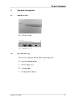
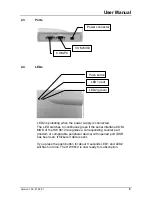
Page 7: ...2 Product description 2 1 HW 8612 views Fig 1 HW 8612 top view Fig 2 HW 8612 back view 2 2 Included delivery The device is shipped with the following components HW 8612 Radio Device Power supply unit 1 serial cable Configuration software ...

Page 8: ...interface COM MOD of the HW 8612 recognises a corresponding counter part modem or comparable peripheral device with opened port DSR has been set It flickers if data is sent If you press the push button for about 3 seconds LED1 and LED2 will flash in turns The HW 8612 is now ready for subscription COM PC COM MOD Power connector Push button LED1 red LED2 green ...

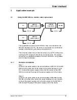
Page 9: ...e no longer necessary 3 1 1 Hardware installation Step 1 Connect one serial cable to the serial interface COM PC of the HW 8612 and the other end of the cable to the serial interface of your PC Connect the power supply unit to the DC socket of the HW 8612 and connect the plug of the power supply unit to the mains Step 2 Connect one serial cable to the serial interface COM MOD of the HW 8612 and th...

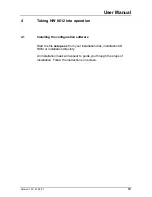
Page 10: ...eration 4 1 Installing the configuration software Start the file setup exe from your installation disk installation CD ROM or installation directory An installation mask will appear to guide you through the steps of installation Follow the instructions on screen ...

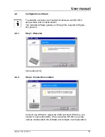
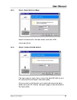
Page 11: ...e station The included software guides you through the required configura tion process 4 2 1 Step 1 Welcome Click button OK 4 2 2 Step 2 Connect base station Connect one HW 8612 Select the COM port the HW 8612 is con nected to Click button OK If the connected HW 8612 is config ured as mobile station the software will configure it as base station ...

Page 12: ...enter a PIN Click button OK 4 2 4 Step 4 Connect mobile station The base station is ready Now connect the other HW 8612 to your PC and select the COM port Click button OK If there is only one COM port in your system disconnect the base station from your PC Ensure the power supply is still connected to the base station ...

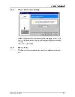
Page 13: ...ion settings Select the baud rate for the mobile station and press the push but ton on your base station until the red and green LEDs are flashing in turns Then click button OK 4 2 6 Step 6 Ready The base and mobile stations are ready for wireless communica tion ...

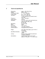
Page 14: ...z Output power 100 mW Standards FCC part 15 247 low power devices op erating at 2400 MHz band EN 300 328 Modulation Gaussian FSK Mode FHSS Duty cycle max 16 67 Data capacity 115 2 kBd protected Antenna system integrated diversity antennas Range up to 300 m free space up to 30 60 m in building Operational elements 1 push button 2 LEDs Casing plastic housing suitable for wall mount or desktop instal...

Page 15: ...Version 1 00 21 06 01 15 ...

Reviews: