21
Section 2:
2.1 Truck Chassis
Overview
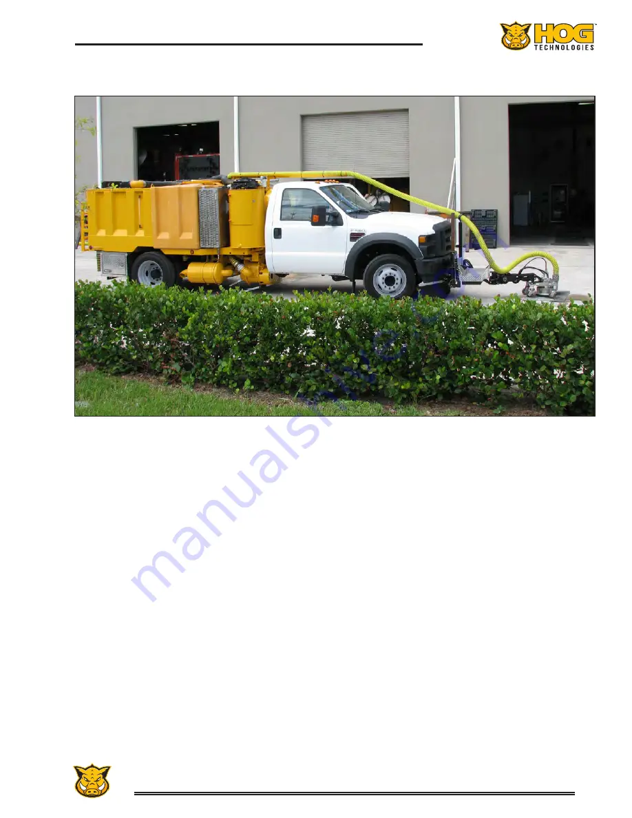
The Stripe Hog SH5500 waterblasting system is
mounted on a truck chassis. The operation and
maintenance requirements for the engine, drive
train and chassis components are unique to the
manufacturer and the selected options. Each truck
chassis manufacturer provides owners information
manuals with their product. It is important that
you read the manuals carefully and become famil-
iar with the proper care and operation of engine,
drive system, chassis, safety equipment and all
components of your truck chassis.
Warranty registration forms are included with the
information manuals. All requested information
on these forms should be filled out completely
and submitted to the dealer or manufacturer as
soon as possible.
Truck Electrical System
Your truck can be equipped with either a 12-volt
or 24-volt DC electrical system depending on
your location and the chassis manufacturer. All
truck chassis are equipped with two heavy duty
main circuit breakers located below the hood on
the driver’s side, just forward of the battery. The
circuit breakers protect the DC circuits that pro-
vide electrical power to the cab control panels and
the electric solenoids that activate the functions
of the PTO, high pressure waterblasting system,
hydraulic system and other electrical equipment
installed by Hog Technologies.
The circuit breakers are equipped with a yellow
indicator/reset lever that indicates the status of
the breaker (ON or OFF) and is used to reset the
breaker if it trips. This is a heavy duty circuit
breaker that typically trips only when there is a
fault in the system. If it trips, you should find and
correct the problem before resetting the breaker.
The breaker is reset by turning the yellow lever
to the “ON” position. Contact Hog Technologies
Customer Service if you need assistance correcting
a problem with the Stripe Hog electrical system.
There is also a fuse panel inside the main control
Stripe Hog Systems
SH5500 Stripe Hog
Summary of Contents for Stripe Hog SH5000
Page 1: ...Operations Manual...
Page 2: ...2...
Page 4: ...4 THIS PAGE WAS LEFT BLANK INTENTIONALLY...
Page 6: ...6 THIS PAGE WAS LEFT BLANK INTENTIONALLY...
Page 8: ...8 THIS PAGE WAS LEFT BLANK INTENTIONALLY...
Page 14: ...14 THIS PAGE WAS LEFT BLANK INTENTIONALLY...
Page 20: ...20 THIS PAGE WAS LEFT BLANK INTENTIONALLY...
Page 50: ...50 THIS PAGE WAS LEFT BLANK INTENTIONALLY...
Page 58: ...58 THIS PAGE WAS LEFT BLANK INTENTIONALLY...
Page 92: ...92 Component Repair THIS PAGE WAS LEFT BLANK INTENTIONALLY...
Page 94: ...94 Component Repair...
Page 96: ...96 Component Repair...
Page 98: ...98 Component Repair...
Page 99: ...99 Fluid End Replacement Parts Appendix A Drawings and Supplies...
Page 100: ...100 THIS PAGE WAS LEFT BLANK INTENTIONALLY...
Page 104: ...104 THIS PAGE WAS LEFT BLANK INTENTIONALLY...
Page 106: ...106 THIS PAGE WAS LEFT BLANK INTENTIONALLY...
Page 110: ...110 THIS PAGE WAS LEFT BLANK INTENTIONALLY...
Page 118: ...118 THIS PAGE WAS LEFT BLANK INTENTIONALLY...
Page 121: ......


