22
22
Stripe Hog Systems
switch panel in the cab. The fuses in this panel
protect the circuits activated by the joystick and
control panel switches.
Refer to the information manual for your truck
chassis for information on the electrical system
on your vehicle.
Video Systems (Optional)
Video systems are optional features that enable
better visibility for the operator while blasting
operations are underway. The video system can
also provide improved visibility while backing the
vehicle. Refer to the truck and video manufactur
-
ers information for instructions on operating and
maintaining video systems.
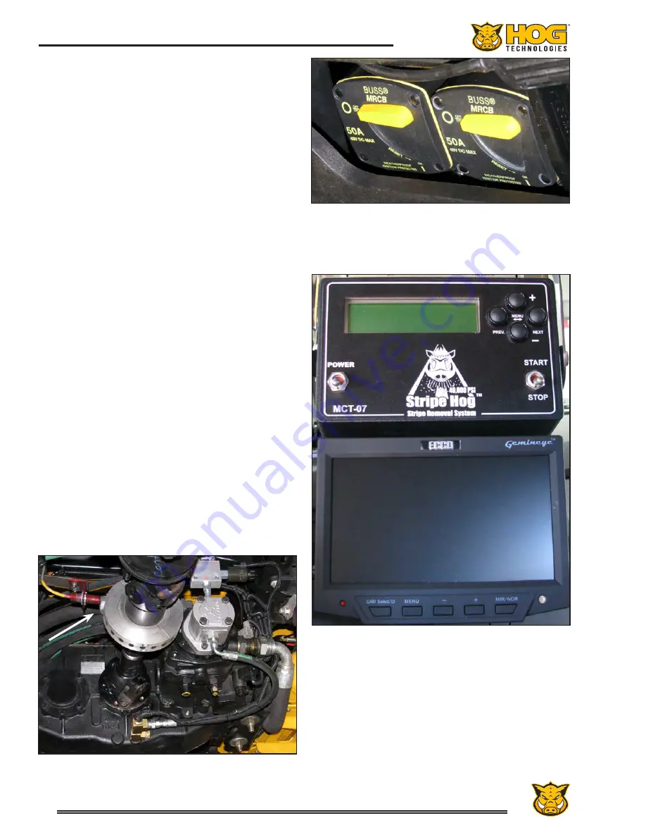
Skip Meter
Most trucks are equipped with a “Skip Meter”
that records the distance traveled while in Work
Mode. When the meter is activated, an inductive
sensor records the revolutions of the truck drive
shaft and converts the readings into linear feet or
meters. The data is recorded and saved until the
operator deletes it.
There are two toggle switches on the front of the
meter. One toggle switch turns the meter ON or
OFF, the other toggle switch is used to start the
meter when blasting operations begin and stop
the meter when operations stop or are paused.
Menu buttons select the meter to read in feet or
meters and various recording and data modes.
An operating manual for the Skip Meter has been
included with your Stripe Hog that provides de-
tailed information on its operation and available
data modes.
Typical Skip Meter Inductive Pickup on Drive Shaft
Skip Meter and Video Screen
Typical Main Circuit Breaker
Located Below the Hood, Forward of the Battery
Summary of Contents for Stripe Hog SH5000
Page 1: ...Operations Manual...
Page 2: ...2...
Page 4: ...4 THIS PAGE WAS LEFT BLANK INTENTIONALLY...
Page 6: ...6 THIS PAGE WAS LEFT BLANK INTENTIONALLY...
Page 8: ...8 THIS PAGE WAS LEFT BLANK INTENTIONALLY...
Page 14: ...14 THIS PAGE WAS LEFT BLANK INTENTIONALLY...
Page 20: ...20 THIS PAGE WAS LEFT BLANK INTENTIONALLY...
Page 50: ...50 THIS PAGE WAS LEFT BLANK INTENTIONALLY...
Page 58: ...58 THIS PAGE WAS LEFT BLANK INTENTIONALLY...
Page 92: ...92 Component Repair THIS PAGE WAS LEFT BLANK INTENTIONALLY...
Page 94: ...94 Component Repair...
Page 96: ...96 Component Repair...
Page 98: ...98 Component Repair...
Page 99: ...99 Fluid End Replacement Parts Appendix A Drawings and Supplies...
Page 100: ...100 THIS PAGE WAS LEFT BLANK INTENTIONALLY...
Page 104: ...104 THIS PAGE WAS LEFT BLANK INTENTIONALLY...
Page 106: ...106 THIS PAGE WAS LEFT BLANK INTENTIONALLY...
Page 110: ...110 THIS PAGE WAS LEFT BLANK INTENTIONALLY...
Page 118: ...118 THIS PAGE WAS LEFT BLANK INTENTIONALLY...
Page 121: ......


