24
24
Stripe Hog Systems
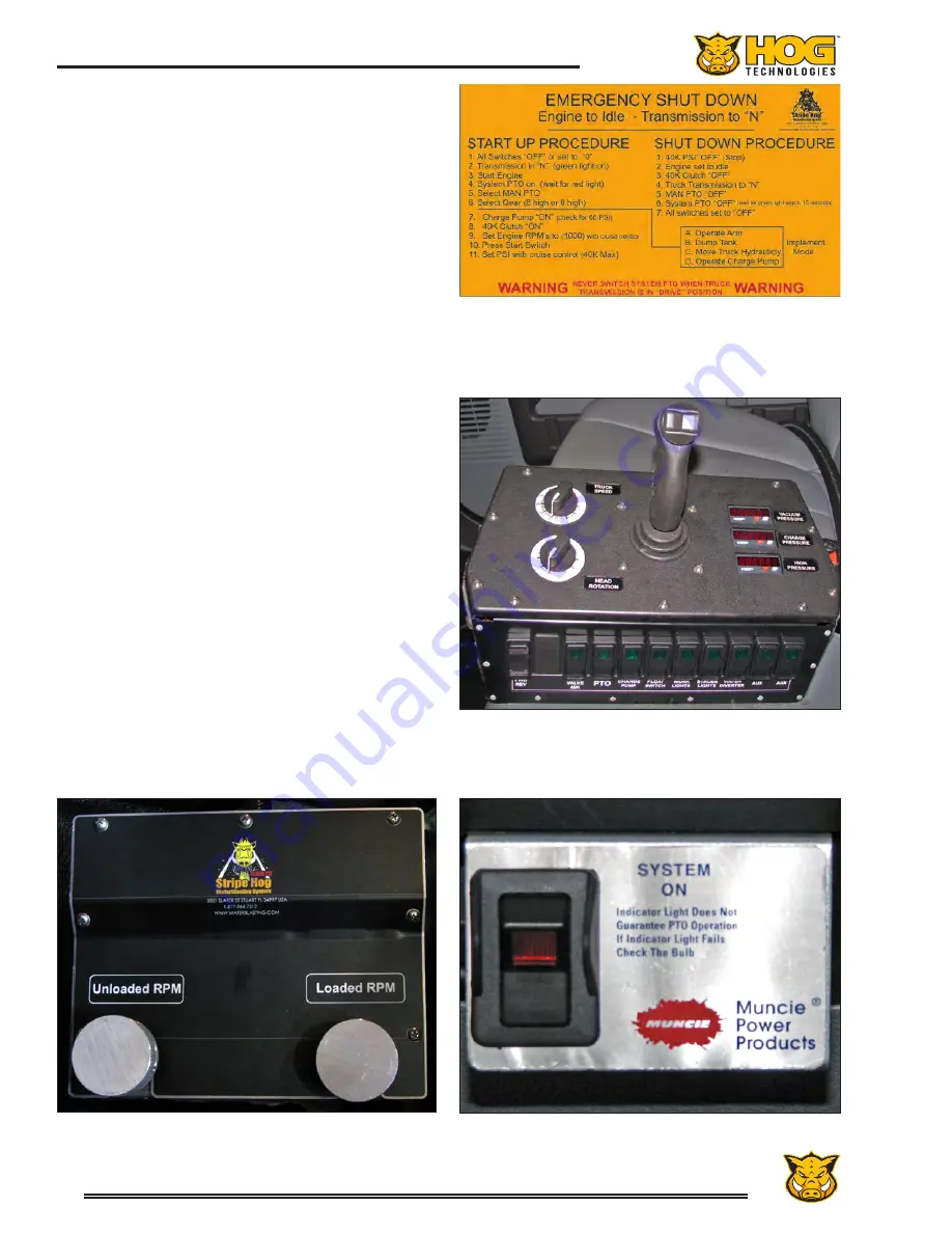
Transmission PTO Switch
Typical In-Cab Instruction Label
INSTRUCTION LABEL SHOWN IS A SAMPLE AND MAY NOT BE THE SAME
AS THE ACTUAL IN-CAB INSTRUCTIONS ON YOUR STRIPE HOG
as there are differences between truck chassis,
transmissions and drivetrains. There are also sig-
nificant differences between foreign and domestic
(USA) truck chassis.
When Work Mode is selected the operator must
depress the clutch and engage the manual trans-
mission in third gear to provide the proper gear
ratio for the transmission and OMSI Drive PTO
systems. When the OMSI Drive PTO switch is
ON, the engine transmission is disconnected from
the differential and the hydrostatic drive system
moves the truck. The TRUCK FWD/REV rocker
switch in the control panel is used to select forward
or reverse. The TRUCK SPEED dial controls the
truck speed in forward or reverse (0 - 7 mph.)
Engine RPM is controlled by the speed dial on the
Remote Engine Control panel on the truck dash
-
board. The Remote Engine Control is activated
or deactivated by an ON/OFF toggle switch on the
panel. Additionally, it can be quickly disengaged
by pressing the brake pedal.
Always make sure the TRUCK FWD/REV rocker
switch in the control panel is in the neutral posi-
tion and the truck speed dial is set to 0 before
engaging the OMSI Drive PTO (PTO switch on the
control Panel) to avoid the possibility for the truck
to surge unexpectedly in forward or reverse when
the hydrostatic drive is engaged.
Indicator lights in the transmission PTO switch
panel and the control panel switches illuminate
when the function is activated. The lights in the
PTO switches are lit when the PTO systems are
engaged.
Control Panel Switches and Joystick
Work Mode Engine Throttle Control
Summary of Contents for Stripe Hog SH5000
Page 1: ...Operations Manual...
Page 2: ...2...
Page 4: ...4 THIS PAGE WAS LEFT BLANK INTENTIONALLY...
Page 6: ...6 THIS PAGE WAS LEFT BLANK INTENTIONALLY...
Page 8: ...8 THIS PAGE WAS LEFT BLANK INTENTIONALLY...
Page 14: ...14 THIS PAGE WAS LEFT BLANK INTENTIONALLY...
Page 20: ...20 THIS PAGE WAS LEFT BLANK INTENTIONALLY...
Page 50: ...50 THIS PAGE WAS LEFT BLANK INTENTIONALLY...
Page 58: ...58 THIS PAGE WAS LEFT BLANK INTENTIONALLY...
Page 92: ...92 Component Repair THIS PAGE WAS LEFT BLANK INTENTIONALLY...
Page 94: ...94 Component Repair...
Page 96: ...96 Component Repair...
Page 98: ...98 Component Repair...
Page 99: ...99 Fluid End Replacement Parts Appendix A Drawings and Supplies...
Page 100: ...100 THIS PAGE WAS LEFT BLANK INTENTIONALLY...
Page 104: ...104 THIS PAGE WAS LEFT BLANK INTENTIONALLY...
Page 106: ...106 THIS PAGE WAS LEFT BLANK INTENTIONALLY...
Page 110: ...110 THIS PAGE WAS LEFT BLANK INTENTIONALLY...
Page 118: ...118 THIS PAGE WAS LEFT BLANK INTENTIONALLY...
Page 121: ......


