34
34
Stripe Hog Systems
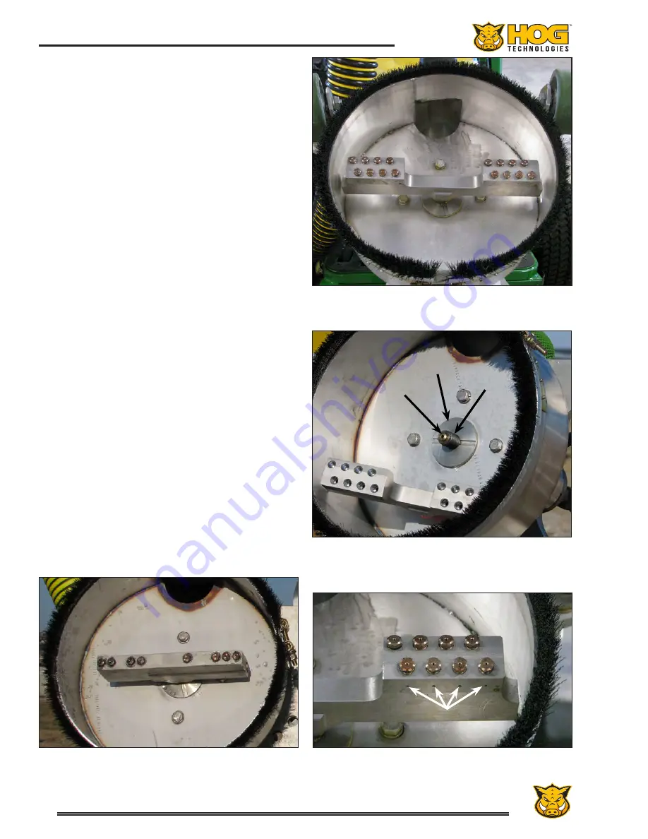
The dirt shield that protects the thru-shaft is
located between the spray bar and blast head
shroud. It consists of a special felt seal that is
held against the bottom of the blast head shroud
by a stainless steel flat washer threaded on the
shaft. The felt seal should be inspected and ad-
justed whenever the spray bar is removed. The
dirt shield should be replaced if it is damaged or
worn and be adjusted “finger tight.” If it is too
tight it will prevent the spray bar from rotating.
With the spray bar installed, operate the pump
at low pressure to check for nozzle accuracy and
leaks on the spray bar or nozzles. Water dripping
from any of the weep holes in the side of the spray
bar indicates that a nozzle is not seated properly.
Leaks at the nozzle seats or thru-shaft threads
must be corrected before beginning high pressure
operations or the spray bar and/or thru-shaft will
be ruined. Should any repairs or adjustments
be necessary, disengage the pump to relieve all
pressure before making any required repairs or
adjustments.
Each spray bar is equipped with a spray bar pro-
tector that is held in place with one or two cotter
pins, depending on the size of the spray bar. The
spray bar protector shields the nozzles and spray
bar from damage caused by debris during blasting
operations. Never waterblast without the spray
bar protector installed. Spray bars and nozzles
are expensive and the life of the nozzles and spray
bars will be dramatically shortened without the
spray bar protector.
16 Nozzle Spray Bar
Spray Bay Removed and Dirt Shield
Button Seal on Thru-Shaft and Anti-Seize on Threads
Spray Bar and Nozzles Installed
Anti-Seize on Nozzle and Spray Bar Threads
Dirt Seal
Button Seal
Anti-Seize
On Threads
Spray Bar with Nozzles Installed and Weep Holes
Weep Holes
Summary of Contents for Stripe Hog SH5000
Page 1: ...Operations Manual...
Page 2: ...2...
Page 4: ...4 THIS PAGE WAS LEFT BLANK INTENTIONALLY...
Page 6: ...6 THIS PAGE WAS LEFT BLANK INTENTIONALLY...
Page 8: ...8 THIS PAGE WAS LEFT BLANK INTENTIONALLY...
Page 14: ...14 THIS PAGE WAS LEFT BLANK INTENTIONALLY...
Page 20: ...20 THIS PAGE WAS LEFT BLANK INTENTIONALLY...
Page 50: ...50 THIS PAGE WAS LEFT BLANK INTENTIONALLY...
Page 58: ...58 THIS PAGE WAS LEFT BLANK INTENTIONALLY...
Page 92: ...92 Component Repair THIS PAGE WAS LEFT BLANK INTENTIONALLY...
Page 94: ...94 Component Repair...
Page 96: ...96 Component Repair...
Page 98: ...98 Component Repair...
Page 99: ...99 Fluid End Replacement Parts Appendix A Drawings and Supplies...
Page 100: ...100 THIS PAGE WAS LEFT BLANK INTENTIONALLY...
Page 104: ...104 THIS PAGE WAS LEFT BLANK INTENTIONALLY...
Page 106: ...106 THIS PAGE WAS LEFT BLANK INTENTIONALLY...
Page 110: ...110 THIS PAGE WAS LEFT BLANK INTENTIONALLY...
Page 118: ...118 THIS PAGE WAS LEFT BLANK INTENTIONALLY...
Page 121: ......


