45
45
Section 2 - Stripe Hog Systems
2.7 Debris Recovery System
Overview
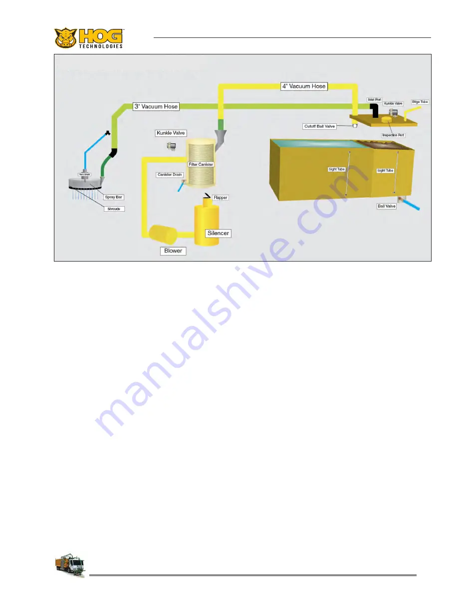
The vacuum system is powered by the main truck
engine and is activated whenever the OMSI Drive
PTO is engaged. The blower creates vacuum in
the filter canister, debris tank, vacuum hoses and
Hog Head. A filter located in the filter canister
protects the blower.
Flexible hoses with quick disconnect fittings pro
-
vide vacuum to the Hog Head shroud. Special
swivel brackets allow the hose to move with the
Hog Head.
The blower bearings require lubrication daily us-
ing special grease specified by the blower manu
-
facturer. Refer to the Lubrication Chart in the
Lubrication & General Maintenance section of this
manual and the blower manufacturer’s manual for
lubrication specifications or additional information
on the operation and maintenance of the blower.
The vacuum is monitored by a digital gauge in the
control panel and an optional gauge on the debris
tank. It is adjusted by increasing or decreasing
the engine RPM. Thus, maximum vacuum, -7
inHg (178 mmHg) is typically achieved at 1800
RPM (Maximum engine operating RPM). Relief
valves (Kunkle valves) on the vacuum filter can
-
ister and debris tank will automatically open if
excessive vacuum in the system occurs. Always
test the valves and all vacuum hose connections
at the start of each shift to ensure the valves are
operating properly and there are no vacuum leaks
in the system.
Blower components have extremely small toler-
ances and must be protected from the debris.
The vacuum filter should be cleaned daily. The
canister is equipped with a door in the side that
provides easy access to the filter and a means to
inspect the canister for excessive debris, water or
to clean the filter. There is a manual drain valve
at the bottom to remove water from the canister
as needed. Make sure the vacuum system is
shutdown before opening the canister door or at-
tempting to drain the water. Never leave the drain
valve open when the vacuum system is operating.
Debris Recovery System
Summary of Contents for STRIPE SH7500
Page 1: ...75 H Operations Manual...
Page 2: ......
Page 72: ...72 NOTES...
Page 108: ...108 NOTES...
Page 161: ...161 Section 5 Scheduled Maintenance...
Page 167: ...167 Appendix 2 Tools Spare Parts...
Page 168: ...168 Appendix 2 Tools Spare Parts...
Page 169: ...169 Appendix 3 Daily Report Pre Op Checklist 1 877 HOG ROAD WWW STRIPEHOGSUPPORT COM 60...
Page 178: ...178 NOTES...
Page 185: ......
Page 186: ......


