14
Adres producenta/ Adresse des Herstellers/ Manufacturer’s Address/ Адрес производителя
GTV Poland Sp. z o.o. Sp. k., ul. Przejazdowa 21, 05-800 Pruszków
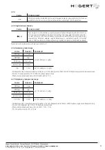
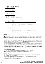
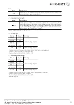
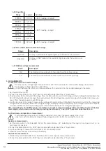
4.2.8 Capacitance
Range
Layout
Accuracy
9,999nF
0,001 nF
± (4.0% r 30 digits)
99,99nF
0,01 nF
± (4.0% r 3 digits)
999,9nF
0,1 nF
9,999µF
0,001 µF
99,99µF
0,01µF
999,9µF
0,1µF
9,999mF
0,001 mF
99,99mF
0,01 mF
± (5.0% r 30 digits)
4.2.9 Non-contact detection of NCV AC voltage
Range
Description
Low field
Display - L, NCV indicator (green) lights up and buzzer issues an alarm
High field
Display - H, NCV indicator (two red LEDs) lights up while the buzzer issues
an alarm
4.2.10 Battery voltage measurement
Reach
Description
1.5 V
The load resistance is about 30 ohms and shows the battery voltage
9 V
The load resistance is about 300 ohms and shows the battery voltage
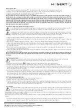
5. MEASUREMENTS
5-1. Measurement of AC and DC voltage
Do not measure a voltage higher than 600 V DC or 600 V AC to avoid electric shock and/or damage to the meter.
Do not apply a voltage higher than 600 V DC or
600 V AC between the common terminal and the earth to avoid electric shock and/or damage to the meter.
1. Set the dial to the icon .
2. Connect the black probe to the „COM” input socket and the red probe to the „V” input socket.
3. The default position in the field is DC voltage. Press the SEL button to switch to AC voltage. In the AC voltage field, hold down the
SEL / VFC button for about 2 seconds, the meter will switch to AC voltage measurement mode, which enables stable measure-
ment. Press the button again to exit VFC mode.
4. Use the two ends of the probe to measure the voltage of the tested circuit. (Parallel to the tested circuit). Get the measured
voltage value on the display. When measuring DC voltage, the display will show the polarity of the voltage to which the red probe
is connected. When measuring AC voltage, press the HZ button to display the voltage frequency value
Note: In the DC mV or AC 9.999 V range, even if there is no input or connection to the probes, sometimes the meter displays
several digits, which is normal. In this case, by shorting the terminals „V” and „COM” the meter can be reset to zero.
5-2. Resistance and capacitance measurement
To avoid damage to the meter or the device under test, disconnect the power supply to the circuit
under test and completely discharge all high voltage capacitors before measuring the resistance.
Resistance measurement:
1. Set the rotary switch to the field „ ”. At first the meter displays „OL”, indicating that the input is in an open circuit, i.e. no
resistance is connected.
2. Connect the black probe to the „COM” input socket and the red probe to the „V” input socket.
3. Use the probe tips to measure the resistance of the circuit being tested.
4. Read the measured resistance value on the display
Capacitance measurement:
1. Rotate rotary switch field „ ”. Press the SEL button to enter capacity measurement mode.
2. Connect the black probe to the „COM” input socket and the red probe to the „V” input socket.


