7
Adres producenta/ Adresse des Herstellers/ Manufacturer’s Address/ Адрес производителя
GTV Poland Sp. z o.o. Sp. k., ul. Przejazdowa 21, 05-800 Pruszków
DC VOLTAGE
RANGE
RESOLUTION
ACCURACY
200 uA
100 nA
±(1.8% of rdg +2D)
2 mA
1 uA
20 mA
10 uA
200 mA
100 uA
±(2.0% of rdg +2D)
10 A
10 mA
±(2.0% of rdg +10D)
Overload protection: Fuse 500mA/250V (range 10A)
MEASURING VOLTAGE DROP: 200mV
RESISTANCE
RANGE
RESOLUTION
ACCURACY
200 Ω
0.1 Ω
±(1.0% of rdg +10D)
2 KΩ
1 Ω
±(1.0% of rdg +4D)
20 KΩ
10 Ω
200 KΩ
100 Ω
2 MΩ
1 KΩ
MAXIMUM OPEN CIRCUIT VOLTAGE: 3 V
OVERLOAD PROTECTION: max 15 seconds 220 V rms.
BATTERY TEST
RANGE
RESOLUTION
INTERNAL RESISTANCE
9 V
10 mV
900 Ω
1.5 V
1 mV
3 KΩ
MEASUREMENT OF DC AND AC VOLTAGE
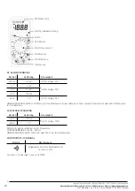
1. Connect the red lead to the „V Ω mA” socket, the black lead to the COM socket.
2. Set the „Function Selection” switch to the needed voltage range if the measured voltage is not known in advance, set the switch to
the highest range and decrease it until a satisfactory reading is obtained.
3. Connect the test leads to the device or circuit to be measured.
4. The voltage value will appear on the display with the voltage polarity.
MEASUREMENT OF DC CURRENT
1. Connect the red lead to the „V Ω mA” socket. The black lead to the COM socket (for measurements between 200mA and 10A, connect
the red lead to 10A socket)
2. Set the „Function Selection” switch to the needed current range.
3. Connect the test leads to the circuit with current.
4. Read the measured value on the display.
5. The „10A” function is intended for intermittent use only. The maximum contact time between the test leads and the circuit is 15
seconds, with a minimum interval between tests of a few seconds.
RESISTANCE MEASUREMENT
1. Connect the red lead to „V Ω mA” socket. The black lead to the COM socket.
2. Set the „Function Selection” switch to the needed Ω range.
3. If the measured resistance is connected to the circuit, turn off the power and discharge all capacitors before the measurement.
4. Connect the test leads to the measured circuit.
5. Read the measured value on the display.
DIODE MEASUREMENT
1. Connect the red lead to „V Ω mA” socket, the black lead to the COM socket.
2. Set the „Function Selection” switch to position”
”
3. Connect the red lead to the anode of the measured diode and the black lead to the cathode.
4. The voltage drop in mV will be displayed.
If the diode is inverted, the number „1” will be displayed.
AUDIO CONTINUITY TEST


