background image

17

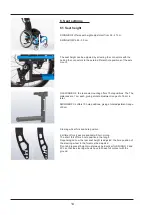
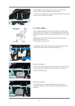
If the SWINGBO 2 is equipped with a wheel cover, this must be

removed before to expose visibly the two rear screws.

To do this, the marked screws must be completely removed. The wheel

cover can then be pulled out upwards.

6.3 Active degree

The active degree describes the ratio of the position of the backrest

relative to the drive wheel axis. The further the backrest is set behind

the the drive wheel axle, the more active SWINGBO 2 and 2 XL can be

driven.

SWINGBO 2 and 2 XL offer an active degree adjustment range of

level 0/1/2/3/4, each 2.5 cm

Total adjustment range is 10 cm

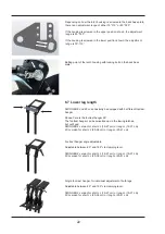
To adjust the active degree, remove the two screws fixing the wheel

cover and loosen the screw of the saddle clamping ring.

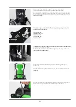
Setting active degree 0

The axle mount is completely extended and the rear screw connection

of the wheel cover is screwed into the rearmost hole of the frame.

This means passive driving.

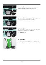
Setting active degree 1

The axle mount is not completely extended and the rear screw

connection of the wheel cover is screwed into the penultimate hole of

the frame.

Summary of Contents for SWINGBO 2

Page 1: ...en SWINGBO 2 2XL Service instructions...

Page 2: ...settings __________________________________________________________________ 14 6 1 Seat height _____________________________________________________________14 15 6 2 Seat depth_______________________...

Page 3: ..._________________________________________________ 35 7 20 Headrest with occiput upholstery ______________________________________________ 35 7 21 Thoracic support _____________________________________...

Page 4: ...e Hoggi GmbH Eulerstr 27 56235 Ransbach Baumbach MADE IN GERMANY 01 04047349096062 21 202178999 3346 10SB XXX SWINGBO 2 Kantelbarer Rollstuhl 2021178999 2021 05 15 max load 50kg Hoggi GmbH Eulerstr 27...

Page 5: ...SWINGBO 2 XL Kantelbarer Rollstuhl 2021178999 2021 05 15 max load 100kg Serial number Classification Product name Year of manufacture UDI Code Manufacturer Place of manufacture Date of manufacture Max...

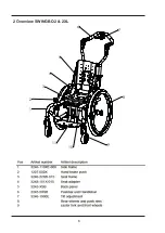
Page 6: ...6 2 Overview SWINGBO 2 2XL 1 2 4 5 6 7 8 9 3 11 10...

Page 7: ...the life of the product Every rehab product should be checked and serviced once a year However it is recommended to check readjust and if necessary service products with a high frequency of use with...

Page 8: ...e used again e g rear wheels steering wheels or push handles Please see also the service manual for detailled information 3 3 Declaration of Conformity HOGGI GmbH as manufacturer declares under sole r...

Page 9: ...first time user Therefore no replacement wheel chair is available in the initial configuration In order to ensure a correct spare parts delive ry the serial no of your wheelchair is required We are ha...

Page 10: ...i de Attention Study the service and maintenance instructions before starting work Attention Use suitable tools see page 4 ff Attention Wear suitable clothing and if necessary gloves and protective go...

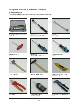
Page 11: ...ratchet and sockets size 8 24 Torque wrench Measuring ranges 5 50 Nm Wrench Size 6 24 Hexagon wrench Gr 3 6 Screwdriver Blade width 2 5 3 5 and 5 5 Phillips screwdriver Size 2 Plastic hammer Hammer a...

Page 12: ...o o o o 1 5 Back system push bar handle variant Height adjustment back Angle adjustment back Height adjustment for push bar handles Angle adjustment for push bar Remove Fold down o o o o o o o o o o o...

Page 13: ...Padding o o o o o 2 10 Headrest with occiput upholstery Height adjustment Angle adjustment Padding o o o o o o o o 2 11 Thoracic support Height adjustment Width adjustment Depth adjustment Padding o...

Page 14: ...long The short fork offers 3 hole positions the long 4 Depending on how the rear seat height is adjusted the hole position of the steering wheel in the fork must be adjusted Front and rear seat heigh...

Page 15: ...ng on the wheel camber steering wheels and drive wheels the following guidelines result for SWINGBO 2 Depending on the wheel camber steering wheels and drive wheels the following guidelines result for...

Page 16: ...e chair is tilted to 45 to reach and loosen the front screw connections The following adjustment ranges result for SWINGBO 2 according to the seat width The following adjustment ranges result for SWIN...

Page 17: ...NGBO 2 and 2 XL can be driven SWINGBO 2 and 2 XL offer an active degree adjustment range of level 0 1 2 3 4 each 2 5 cm Total adjustment range is 10 cm To adjust the active degree remove the two screw...

Page 18: ...rear wheel cover wheel cover is screwed into the third last hole of the frame Setting active degree 3 The axle mount is extended relatively short and the rear wheel cover is screwed into the fourth la...

Page 19: ...ffers the following ranges The trough back offers the following adjustment ranges depending on the seat width for SWINGBO 2 and SWINGBO 2XL Seat width SW 24 26 28 30 32 34 36 Backrest height back trou...

Page 20: ...l is screwed to the base the adjustment range is either 75 115 or 80 120 If the back plate is screwed in the positions shown on the left the adjustment range is 80 120 If the backrest panel is screwed...

Page 21: ...shed upwards and then the back is folded down Angle adjustable and foldable push bar with trough shaped backrest As with the foldable push handles bar only the moulded backrest can be used Push bar ha...

Page 22: ...nd 160 via clamping lever SWINGBO 2 version for short LL 19 27 cm or long LL 19 37 cm 2XL version for short LL 20 36 cm or long LL 20 41 cm Single foot rest hanger for individual adjustment of both le...

Page 23: ...e footrest and thus also the footrest angle The further the footrest is pulled out to the front the the greater the angle If the procedure is reversed the angle decreases accordingly 6 9 Armrest heigh...

Page 24: ...w connections To loosen the screws first tilt the chair to 45 Then the front screws can be loosened first By using a different hole position the general angle of inclination can also be adjusted If th...

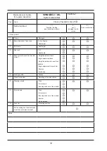
Page 25: ...general damage Check of the screw connections Screw connections to the cross tube Connection of the side panels to the frame and to the internal adapter plates Check of the screw connections Clamping...

Page 26: ...bar handle variant Functional test Check for general damage Back panel height adjustable and foldable Push handles or push bar removable or foldable Ratchet joint function for push handles Release of...

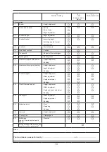
Page 27: ...the seat Backrest panel in trough shape Screw connection to the backrest height adjustment and to the clamps on the push handles Connection to the seat adapter Connection via support strut to seat ad...

Page 28: ...Visible damage 7 6 Braking system Knee lever brakes Functional test Brake closure Faultless operation Visible damage Brake closed Check of the screw connections Fixing the brake to the frame Integrat...

Page 29: ...3 4 5 7 10 11 8 8 9 2 2 1 Check of the screw connections Connection brake anchor with adapter Connection of brake anchor adapter with side plate Bowden cable correctly hooked in Screw connection of th...

Page 30: ...hecking the running behaviour of the wheel clearance mechanics of the axle Checking of the correct alignment of the camber adapter and its bolting Adjustment of the quick release axle The axle should...

Page 31: ...onnection to base plate firmly tightened Armrest holder firmly screwed to wheel cover Fender with integrated brake system and armrests Functional test Check for general damage Height adjustment and la...

Page 32: ...l test Check for general damage Swivel mechanism Clamping lever for angle adjustment Screw connection to the seat plate 7 14 Footrest bracket Standard Functional test Check for general damage Swivel m...

Page 33: ...Functional test Check for general damage Screw connection to the footrest holder Foot rest with heel stop Functional test Check for general damage Screw connection to the footrest holder Single footpl...

Page 34: ...r general damage Velcro fastening seams holes or strapped through areas Check for contamination Seat cushion contoured Check for general damage Velcro fastening seams holes or strapped through areas C...

Page 35: ...wear cracks etc Clamping ability Checking the screw connections Attachment of pad to support 7 19 Headrest standard Functional test Check for general damage Checking the screw connection to the back p...

Page 36: ...for general damage Screw connection of the upholstery to the armrest support Connection of the armrest support to the seat mounting and to the tilt bearing Armrests with tilt compensation Functional t...

Page 37: ...of the screw connection of the bracket 4 point lap belt Functional test Check for general damage Check of the fastener Check of the screw connection of the bracket Ankle hugger Functional test Check f...

Page 38: ...e Back angle and height adjustable 75 115 or from 80 120 in 10 steps Foldable push bar handles 85 105 in 5 steps Lower leg length 16 37 cm Footrest angle 10 up to 10 Seat height 36 47 cm Rear wheel di...

Page 39: ...39...
Page 40: ...HOGGI GmbH Eulerstra e 27 56235 Ransbach Baumbach Deutschland Telefon 49 2623 92 499 0 Telefax 49 2623 92 499 99 E mail info hoggi de www hoggi de by HOGGI GmbH_1910 2049 EN_11_2021...

Reviews: