background image

A S S E M B LY

I N S T R U C T I O N S

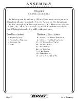
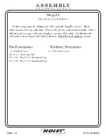
F R A M E A S S E M B L Y

Step 2f

FITNESS SYSTEMS

R

HOIST

In this step start by sliding one (30) on both handles on (6). Then,

slide on one (31) on each side. Place (29) on the end of the handle. Once

all three pieces (per side) are in place, secure (29), slide (31) flush with

(29) and secure. Insert all (28) as shown.

screws.

Allen Wrench tighten

6 - Arm Rest Assy.

28 - 2” x 3” End Cap (VH)
29 - 1 1/4” Dia. X 3/4” Aluminum Cap
30 - 1 1/4” Dia. X 3/4” Aluminum Ring

Part Descriptions

L - #10-32 Set Screw

Hardware Descriptions

2412 Assembly

Page 15

Summary of Contents for CL-2412

Page 1: ...th Serial Number and Model Number are Required when Ordering Parts July 2000 OWNERS MANUAL RECORD SERIAL NUMBER HERE Customer Service Fax 800 548 5438 619 578 7676 619 578 9558 CL 2412 FITNESS SYSTEMS R HOIST ...

Page 2: ...ly Page 1 INSTRUCTIONS Step 1 FRAME ASSEMBLY Step 2 PARTS LISTING HARDWARE LISTING BOLT SIZING CHART WASHER SIZING CHART WEIGHT RATIOS WEIGHT TRAINING TIPS WEIGHT TRAINING EXERCISE LOG DECAL PLACEMENTS GENERAL MAINTENANCE INFORMATION LIMITED WARRANTY 2 4 23 24 26 27 28 30 32 34 39 42 ...

Page 3: ...icing Failure to do so will void your warranty and could result in personal injury Hoist equipment is designed to provide the smoothest most effective exercise motion possible After assembly you should check all functions to ensure correct operation If you experience problems first recheck the assembly instructions to locate any possible errors made during assembly If you are unable to correct the...

Page 4: ...FITNESS SYSTEMS R HOIST A S S E M B LY I N S T R U C T I O N S FITNESS SYSTEMS R HOIST Page 3 2412 Assembly ...

Page 5: ...p 2 FITNESS SYSTEMS R HOIST FACTORY INSTALLATION INSTRUCTION ONLY 1 ALL THREADED HOLES SHOULD BE TAPPED EXCEPT INSERTS 2 ALL CALLED OUT INSERTS MUST BE INSTALLED BEFORE ANY ASSEMBLY 3 PUT A DROP OF ON BOLTS IF NECESSARY 4 IF NECESSARY APPLY TO ALL BEARINGS BLUE LOCTITE 242 GREEN LOCTITE 680 ...

Page 6: ...7 Next attach 8 to 6 bolts only they will be tightened later Lift machine to position 14 Hand Tighten 5 Weight Cage Assy 6 Arm Rest Assy 7 Cross Connector Assy 8 Foot Plate Assy 14 Rubber Foot Plate Part Descriptions A 1 2 13 x 1 1 2 Button Head Screw AA 1 2 Internal Lock Washer AG 1 2 Flat Washer CB 1 2 Insert Hardware Descriptions 2412 Assembly Page 5 ...

Page 7: ...A S S E M B LY I N S T R U C T I O N S Page 6 2412 Assembly FITNESS SYSTEMS R HOIST 5 6 14 14 14 14 CB CB CB CB 7 8 CB A A A A A A A A A AA AA AA AA AA AA AA AA AG 14 AG AG AG AG AG AG AG ...

Page 8: ...en secure 16 and 9 with CN After 9 is secure to 5 attach K to both ends of 16 bolts only they will be tightened later Hand Tighten 5 Weight Cage Assy 9 Pivoting Foot Plate Assy 15 Aluminum Cap 16 Shaft Part Descriptions B 3 8 16 x 1 1 4 Button Head Screw K 3 8 16 x 1 Flat Head Cap Screw AC 3 8 Internal Lock Washer AH 3 8 Flat Washer AJ 3 8 Flat Washer BA 3 8 Lock Nut CC Plug Bumper CM Flange Beari...

Page 9: ...A S S E M B LY I N S T R U C T I O N S Page 8 2412 Assembly FITNESS SYSTEMS R HOIST 15 15 16 5 B B AH B B B B K K CN CM AC AH AH AH AH AJ AJ AJ AJ AJ AJ AJ AJ BA BA BA BA BA BA CC CM 9 AH AC AC AC AC AC ...

Page 10: ...ing all previously hand tightened bolts Wrench tighten 2 Center RH BRK Add On 5 Weight Cage Assy 17 Guide Rod 18 8 6 lbs Top Plate 19 20 lbs Intermediate Weight 20 Weight Bumper 21 Guide Rod Bushing 22 Weight Selector Pin 23 Add On Weight 24 5 lbs Add On Weight 39 Add On Weight Bushing Part Descriptions C 3 8 16 x 2 3 4 Button Head Screw D 5 16 18 x 1 Button Head Screw E 3 8 16 x 1 Button Head Scr...

Page 11: ...I N S T R U C T I O N S Page 10 2412 Assembly FITNESS SYSTEMS R HOIST 2 17 17 18 19 20 20 21 21 22 23 24 5 C AB AB D E AC AD AE AE AH AJ F AK CA CF CE SEE PAGE 12 FOR TOP WEIGHT STEM ASSEMBLY AJ AJ C 23 39 23 39 39 39 ...

Page 12: ... R A M E A S S E M B L Y Step 2d FITNESS SYSTEMS R HOIST Slide 25 up into 18 and secure with CD bolts Wrench tighten 18 8 6 lbs Top Plate 25 Stem 16 Holes Part Descriptions CD 7 16 x 3 Open Roll Pin Hardware Descriptions 2412 Assembly Page 11 ...

Page 13: ...A S S E M B LY I N S T R U C T I O N S Page 12 2412 Assembly FITNESS SYSTEMS R HOIST CD 18 25 ...

Page 14: ...hrough the slot keeping the loop open Fig 3 Next slide 38 through CK and line up the holes then secure to 1 Next attach the belt by bringing it up through the hole on 5 See on page 14 bolts Detail Belt Set Up Wrench tighten 1 Belt Anchor Adjustable Part Descriptions G 3 8 16 x 1 Button Head Screw M 1 4 20 x 1 1 2 Socket Head Cap Screw P 1 4 20 x 1 Button Head Screw AD 3 8 Internal Lock Washer AJ 3...

Page 15: ...M M AD AD AD AD AD AD AJ AJ AJ AJ AJ AJ AN AN AM AM BB CG CG CK CL SEE VIEW 1 SEE VIEW 1 5 VIEW 1 VIEW 1 FIGURE 1 FIGURE 1 FIGURE 3 FIGURE 3 FIGURE 2 FIGURE 2 38 AM P P AM 1 NOTE 1 BELT SMOOTH SIDE DOWN ALWAYS FOR TWO TOP PULLEYS AND CLAMP SMOOTH SIDE TO WRAP AROUND BELT RETAINER SHAFT 2 WHEN TIGHTENING THE CLAMPS 26 TO THE BELT DO NOT EXCEED 70 IN LBS ...

Page 16: ...ne 31 on each side Place 29 on the end of the handle Once all three pieces per side are in place secure 29 slide 31 flush with 29 and secure Insert all 28 as shown screws Allen Wrench tighten 6 Arm Rest Assy 28 2 x 3 End Cap VH 29 1 1 4 Dia X 3 4 Aluminum Cap 30 1 1 4 Dia X 3 4 Aluminum Ring Part Descriptions L 10 32 Set Screw Hardware Descriptions 2412 Assembly Page 15 ...

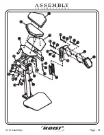
Page 17: ...A S S E M B LY I N S T R U C T I O N S Page 16 2412 Assembly FITNESS SYSTEMS R HOIST 28 28 28 29 30 30 29 31 31 6 L L L L L L L L ...

Page 18: ...32 to 4 Finally attach 41 10 and 40 11 to 6 as shown bolts Wrench tighten 3 Latch Assy 4 Mid Chest Chrome Adjuster 6 Arm Rest Assy 10 Right Arm Upholstery Assy 11 Left Arm Upholstery Assy 12 Mid Chest Upholstery Assy 13 Mid Chest Upholstery Backing 32 1 1 2 x 3 1 2 End Cap 33 EZ Glide Sleeve 34 1 55 x 25 dia Shaft 35 Adjuster Spring 40 Left Hand Upholstery Backing 41 Right Hand Upholstery Backing ...

Page 19: ...A S S E M B LY I N S T R U C T I O N S Page 18 2412 Assembly FITNESS SYSTEMS R HOIST 3 4 10 6 12 13 32 33 34 35 H H H H J J J J N AF AF AF AF AF AF AF AF AL AL AL AL AL AL AL AL CJ 40 41 11 ...

Page 20: ...T In this step use a spray can of by spraying an X pattern and also around the edges on both foot plates Spray the same procedure on the back of 36 Then attach 36 to the foot plate Contact 80 Neoprene Adhesive 36 Rubber Foot Plate Pad Part Descriptions Hardware Descriptions 2412 Assembly Page 19 ...

Page 21: ...A S S E M B LY I N S T R U C T I O N S Page 20 2412 Assembly FITNESS SYSTEMS R HOIST 36 36 ...

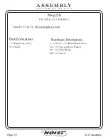
Page 22: ...M B L Y Step 2b FITNESS SYSTEMS R HOIST Attach 37 to 5 bolts Wrench tighten 5 Weight Cage Assy 37 Shield Part Descriptions A 1 2 13 x 1 Button Head Screw AA 1 2 Internal Lock Washer AG 1 2 Flat Washer CB 1 2 Insert Hardware Descriptions 2412 Assembly Page 21 ...

Page 23: ...A S S E M B LY I N S T R U C T I O N S Page 22 2412 Assembly FITNESS SYSTEMS R HOIST A AA AG 5 AG AA A A AG AA AG AA A 37 ...

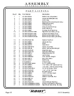
Page 24: ...aft 17 2 26 STD SG135 Guide Rod 18 1 26 STD SWTOP12 8 6 lbs Top Plate 19 15 26 STD SW104 20 lbs Intermediate Weight 20 2 26 STD PLAS201 Weight Bumper 21 2 26 STD PLAS134 Guide Rod Bushing 22 1 26 STD SM134 Weight Selector Pin 23 2 26 STD SM295 Add On Rod 24 3 26 STD SWADD7 5 lbs Add On Weight 25 1 26 STD SW111 Stem 16 Holes 26 4 26 STD SP467 Belt Clamp 27 1 018 0002005 2 Belt Pulley 28 3 26 STD PL...
Page 25: ...0 x 1 Button Head AA 12 13 LOK 12INT 1 2 Internal Lock Washer AB 2 13 LOK 38WZ 3 8 Split Washer AC 9 13 LOK 38INTB 3 8 Internal Lock Washer AD 7 13 LOK 38INT 3 8 Internal Lock Washer AE 2 13 LOK 516INTB 5 16 Internal Lock Washer AF 8 13 LOK 516INT 5 16 Internal Lock Washer AG 12 13 FLT 12SAEWZ 1 2 Flat Washer AH 9 13 FLT 38SAE 3 8 Flat Washer AJ 9 13 FLT 38SAEWZ 3 8 Flat Washer AK 2 13 FLT 516SAE ...

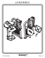
Page 26: ...FITNESS SYSTEMS R HOIST A S S E M B LY M A N U A L FITNESS SYSTEMS R HOIST Page 25 2412 Assembly ...

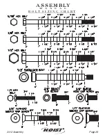
Page 27: ...FITNESS SYSTEMS R HOIST 2412 Assembly Page 26 A S S E M B LY M A N U A L B O L T S I Z I N G C H A R T ...

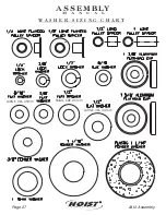
Page 28: ...FITNESS SYSTEMS R HOIST 2412 Assembly Page 27 A S S E M B LY M A N U A L W A S H E R S I Z I N G C H A R T SMALL SAE 26mm LARGE USS 34mm LARGE USS 25mm ...

Page 29: ...ows the actual weight you are lifting when the ratios are applied To find the actual weight you are lifting you would come down from the ratio being used and across from the number of the weight plate you have pinned 45 45 1 4 2 13 3 22 4 35 5 48 6 61 7 74 8 87 9 100 10 113 11 126 12 139 13 152 14 165 15 178 16 191 ...

Page 30: ...FITNESS SYSTEMS R HOIST FITNESS SYSTEMS R HOIST Page 29 2412 Assembly A S S E M B LY M A N U A L ...

Page 31: ...re your body for the heavier workload of lifting weights Learn how to perform the exercise correctly before using heavy weight Correct form is important to avoid injury and to ensure that you work the proper muscle groups Know your limitations If you are new to weight training or are embarking on an exercise regimen after a long layoff start slowly and build foundational strength over a longer per...

Page 32: ...FITNESS SYSTEMS R HOIST FITNESS SYSTEMS R HOIST Page 31 2412 Assembly A S S E M B LY M A N U A L ...

Page 33: ... HOIST 2412 Assembly Page 32 Weight Training Exercise Log S R W Sets Repetition per set Weight used S S Exercise Totals S S S S S S S S S S R R R R R R R R R R R R W W W W W W W W W W W W Date A S S E M B LY M A N U A L ...

Page 34: ...FITNESS SYSTEMS R HOIST FITNESS SYSTEMS R HOIST Page 33 2412 Assembly A S S E M B LY M A N U A L ...

Page 35: ... SYSTEMS R HOIST 2412 Assembly Page 34 D E C A L P L AC E M E N TS 1 021 0004026 2 021 0003008 3 021 0004029 4 021 0004032 5 021 0003011 6 021 0003006 7 021 0012004 8 021 0003079 9 021 0003090 Decal Descriptions 1 3 5 2 9 7 4 8 3 6 ...

Page 36: ... e e k l y Y e a r l y M o n t h s 6 Inspect Links Pull Pins Snap Locks Swivels Weight Stack Pins Clean Upholstery Lubricate Guide Rods with Waylube Oil only Inspect Accessory Bars and Handles Inspect All Decals Inspect All Nuts and Bolts Tighten if Needed Inspect Anti Skid Surfaces Inspect Cables or Belts Tension Lubricate Seat Sleeves Turcite Bushings Linear Bearings Clean and Wax All Glossy Fin...

Page 37: ... instructions before using this equipment Inspect equipment for loose worn or frayed parts If in doubt about a certain part use this machine Keep hands and feet away from moving parts attempt to free any jammed part by yourself Stop your workout immediately if you feel faint or dizzy Warm up before and cool down after engaging in weight resistance training Take your time and don t rush the exercis...

Page 38: ...ertain part use the machine until the part is replaced Failure to replace worn parts may result in injury to free any jammed part by yourself Obtain assistance as the part may free itself suddenly causing possible injury 4 BE CERTAIN DO NOT BE CARELESS 5 6 CHILDREN SHOULD NOT BE ALLOWED TO USE THIS EQUIPMENT 7 HOIST to keep your head hands and limbs clear of moving parts Be alert to the possibilit...

Page 39: ...S M A N U A L R HOIST D E C A L R E F E R E N C E This decal has been attached to this piece of equipment to provide information regarding operation safety and maintenance Before use take the time to read these decals 021 0003090 PATENT PENDING 021 0004026 ...

Page 40: ... Wipe clean with a clean dust free rag If lubrication is required lube with or damage to the Top Weight Bearing may occur DO NOT repeatedly clean the shafting with alcohol or any other stripping cleanser The Top Weight Bearing transfers a gliding material to the guide rods Cleaning other than wiping with a clean dust free rag will remove the previously transferred material and increase the wear to...

Page 41: ...cant Lubricate seat sleeves and oilites with a Silicon or Teflon based lubricant spray Referring to the Assembly Owners manual carefully dis assemble the bearing from its housing and place a finger full of light grease lithium super lube etc into the inside of the bearing Using your finger press the grease into the ball bearings and their tracks Repeat until the ball bearing tracks are full of gre...

Page 42: ...FITNESS SYSTEMS R HOIST FITNESS SYSTEMS R HOIST Page 41 2412 Assembly A S S E M B LY M A N U A L ...

Page 43: ...s other than expressly covered by this warranty NO CONSEQUENTIAL DAMAGES Hoist is not responsible for economic loss profit loss or special indirect or consequential damages WARRANTY IS NOT TRANSFERABLE This warranty is not assignable and applies only in favor of the original purchaser user to whom delivered Any such assignment or transfer shall void the warranties herein made and shall void all wa...

Reviews: