background image

6

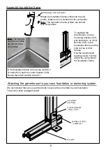
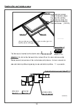
Note: The founda-

tion frame profiles

are shorter than 

soil profiles

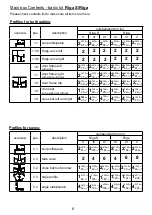
Attaching the greenhouse to your own foundation or anchoring system

We recommend that you use anchor bolts to


secure the soil profile to your foundation.

The anchor bolts are 

not

 included.

side profile/

door frame

mounting bracket

- offset - (V

5)

bolt M6 x 

2 (S

2)

+ nut M6 (S

)

soil profil

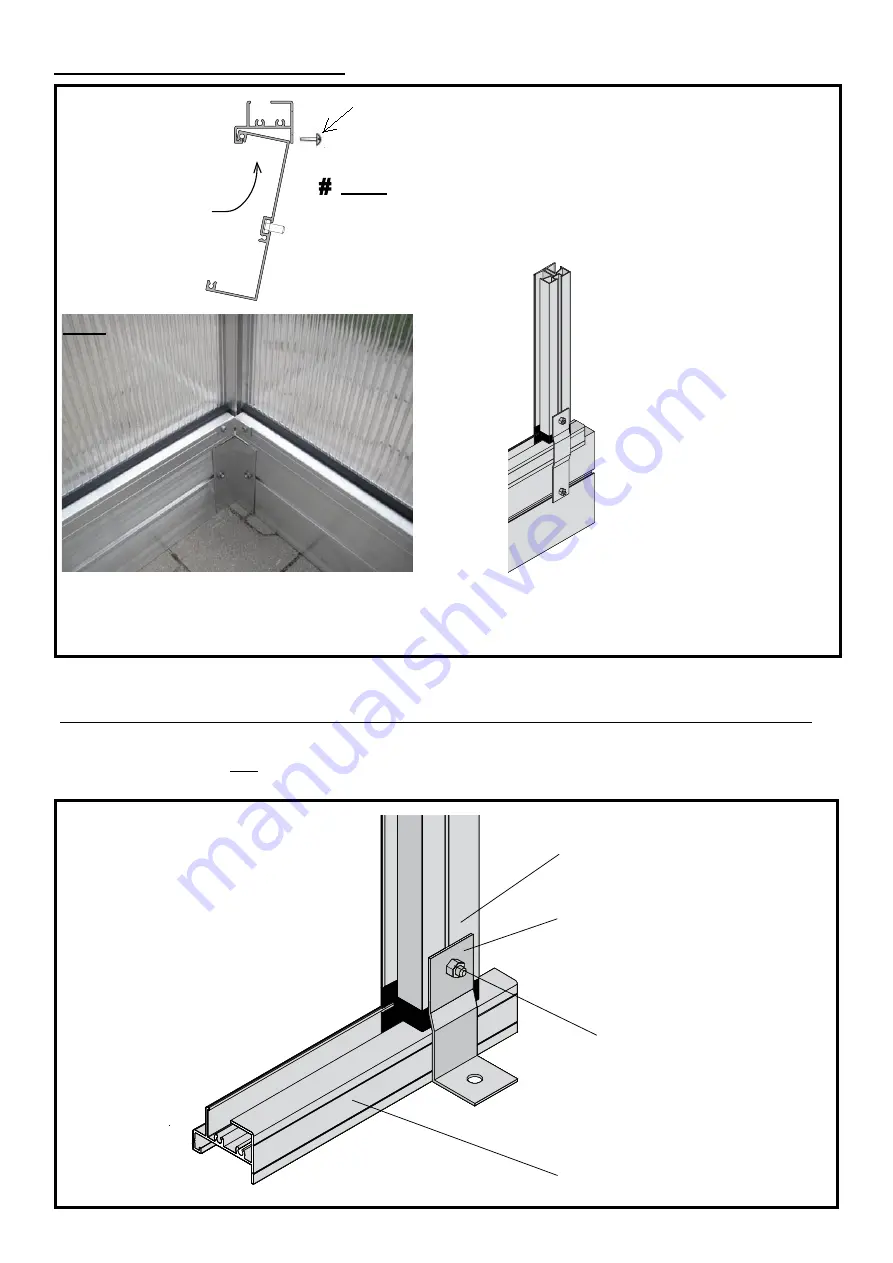
Rotate the foundation frame profile into the soil 

profile.  Make sure it is centered in the soil profile.

N

ote:

 The foundation frame profiles are shorter

than soil profiles

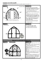
To stabilize the 

greenhouse, use the 

mounting bracket (V27) 

with

 bolts M6 x 2 (S2) 

Bolt the (V27) to the 

foundation frame and the 

side curves or door 

frames.

Use the supplied self 

tapping screws to firmly 

attach the soil profile to 

the foundation frame.

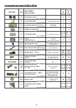
In the foundation frame corners use two M6 x 

2

 bolts

 (S2) 

and one corner bracket (V26) 

Fasten them with two M6 nuts

 (S).

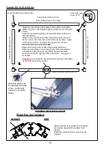
Assembly foundation frame

Self-tapping screw placement

Summary of Contents for Riga

Page 1: ...ct to technical changes model Riga S Width 2 32 m 7ft 8in www exaco com 877 760 8500 customerservice exaco com Assembly Animation Video is available on our YouTube page find the link at www exaco com or scan the QR code below model Riga Width 2 96 m 9ft 8in Version 4 2021 ...

Page 2: ...5 16 Wind Restraints for High Wind optional 17 Door Assembly Door Bottom Half 18 19 Door Top Half 20 21 Door Catch Installation 22 Rear Window 23 24 Putting It All Together Assembling the Eaves Sidewalls 25 27 Installing roof windows doors 27 Polycarbonate Size Count Sheet 28 Optional Accessories may not be included with your kit Riga Top Shelf 29 32 Riga Bottom Table Shelf 33 36 Exhaust Fan Insta...

Page 3: ...vent injury or damage do not attempt assembly of this greenhouse in windy conditions It is dangerous to leave a greenhouse partially assembled Damages during assembly process due to bad weather are not covered by our warranty Assembly Much of the assembly can be done by one person but it is most helpful to have a second pair of hands available Assembling the windows doors and gables ahead of time ...

Page 4: ...ions You may also create your own insertion point as needed with a 1 2 drill bit This will not compromise the integrity of the structure Quantity of wedge seals pos 4 2 pos 4 1 pos 3 3 p o s 1 5 6 pos 2 1 pos 2 3 1 pos 2 3 1 pos 1 1 pos 1 9 pos 1 9 pos 1 5 4 p o s 1 5 4 pos 1 5 6 pos 1 7 pos 1 6 pos 1 8 pos 3 2 IMPORTANT Quantity of cartons basic construction gable eaves curved center profile wind...

Page 5: ...e most common silicone sealant Neutral cure silicone is available in most hardware stores We recommend Boss 399 You can purchased Boss 399 directly from us just call 1 877 760 8500 Cleaning and care To wash the greenhouse use plenty of water a soft car wash brush and a little mild dish soap Palmolive works well Note Important information for glazing When installing the polycarbonate glazing make s...

Page 6: ...embled to check for level and square This is not final and will need to be disassembled Do not permanently attach corners or fill in the gable end trenches with dirt The side wall trenches can be partially filled with dirt Once this step has been completed go to Step 1 on page 10 The optional Riga foundation frame is the easiest and the safest foundation for a greenhouse It requires no concrete AT...

Page 7: ...ion frame profile into the soil profile Make sure it is centered in the soil profile Note The foundation frame profiles are shorter than soil profiles To stabilize the greenhouse use the mounting bracket V27 with bolts M6 x 2 S 2 Bolt the V27 to the foundation frame and the side curves or door frames Use the supplied self tapping screws to firmly attach the soil profile to the foundation frame In ...

Page 8: ...he corners are square This will prevent any errors in measurement Foundation plan Riga S Riga Construction with a perimeter or strip foundation 249cm 98 1 16 249cm 98 1 16 312cm 12213 16 312cm 12213 16 312cm 12213 16 232cm 91 5 16 338cm 133 1 16 443cm 174 7 16 338cm 133 1 16 443cm 174 7 16 549cm 216 1 8 233cm 91 3 4 233cm 91 3 4 233cm 91 3 4 296cm 116 9 16 296cm 116 9 16 296cm 116 9 16 216cm 851 1...

Page 9: ...2 2 2 2 2 2 2 2 2 2 73 7 8 1876mm 2 73 7 8 1876mm 2 73 7 8 1876mm 2 73 7 8 1876mm 2 73 7 8 1876mm 2 73 7 8 1876mm 2 811 16 2059mm 2 811 16 2059mm 2 811 16 2059mm 2 811 16 2059mm 2 811 16 2059mm 2 811 16 2059mm 2 2913 16 758mm 2 2913 16 758mm 2 2913 16 758mm 2 2913 16 758mm 2 2913 16 758mm 2 2913 16 758mm 2 2913 16 758mm 1 2913 16 758mm 1 2913 16 758mm 1 2913 16 758mm 1 2913 16 758mm 1 2913 16 758m...

Page 10: ... head 4 2x13 door frame soil profile cover plate corner V12 38 38 S 3 4 8 x 45 gable 6 6 S5 S1 hexagonal screw M6 x 6 nut bolts for construction of greenhouse II 40 III 40 IV 44 III 40 IV 44 V 48 V15 mounting bracket offset 74 x 30 x 33 mm for the attachment of the greenhouse to a foundation made by customer not with foundation frame 10 10 S32 washer A6 4 door frames roof and side profiles 20 20 V...

Page 11: ...1 7 up to the small holes in the middle of pos 1 1 soil profile The chamfered edge must be facing to the outside Then attach the soil profile corner V9 to the ends of the soil profile step 2 to step 2 Now you need the small side glazing Slide the side glazing into the door frames and soil profile The dimensions are listed in the diagram Note After the door is mounted and aligned attach pos 1 6 and...

Page 12: ...o step 6 The cross bars pos 9 are mounted horizontally with the pan head screw 4 8 x 45 S 3 step 7 view from outside to step 7 Slide the upright profiles pos 1 6 1 7 into the soil profile Insert the 787 x 728 mm glazing between the upright profiles pos 1 6 1 7 Insert one M6 x 16 S5 into each upright profile pos 1 6 1 7 Insert four M6 x 16 S5 into the cross bar pos 1 8 Insert one M6 x 16 S5 into ea...

Page 13: ...is bundled in one strand for all doors and windows please cut accordingly Gasket Notes T seal V25 is for all doors and windows total 5 meters 49 feet long flap goes towards exterior Attention The T seal V25 is only inserted on three sides of the roof window The top side slides into the roof beam so no seal is required In the door threshold the hose section V14 is pressed into the soil profile This...

Page 14: ...tal corners with grub screws Insert the roof window glazing into the side bottom profiles you have assembled Attach the top roof window profile tighten all grub screws and insert T seal on the three lower sides of the roof window Angle cut the ends of the T seal where they meet at the corners Seal with silicone to prevent leaks Apply silicone to the short ends of the window extrusions before inser...

Page 15: ... the sketch above Attention Do not cut the flat seal in the corners Run it in one continuous strip Please seal all connections of the roof window with silicone Corner connector to side and bottom profile and glazing to side and bottom profiles see sketch Seal with silicone around frame side curve pos 2 3 cross bar pos 3 2 window profile pos 4 und 4 2 pos 4 1 Also use silicone to seal between the c...

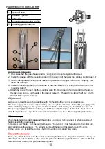
Page 16: ...late 5 5 Attach the opener frame 1 to the mounting plate 5 Open the roof window until the threads of the piston 2 engage the threads of the opener frame 1 Thread the piston 2 half way into the threads in the opener frame 1 Let the opener acclimate to the greenhouse for 3 4 hours before you make adjustments For earlier engagement and a larger opening turn the cylinder clockwise For a delayed engage...

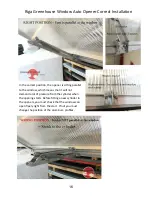
Page 17: ...demand a lot of pressure from the cylinder when the opening starts Before fitting a new cylinder to the openers you must check that the window can open freely right from the start If not you must change the position of the aluminum profiles Riga Greenhouse Window Auto Opener Correct Installation 16 ...

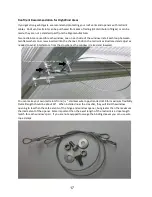
Page 18: ...straint as illustrated and adjust as needed to avoid interference from the crossbar as the window is raised and lowered You can make your own restraints from 1 16 stainless wire rope stranded 7x19 for maximum flexibility Overall length should be about 16 When installed near the crossbar they will limit the window opening to less than the safe extents of the hinge and window opener but greater than...

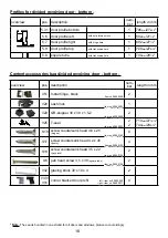
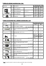
Page 19: ... countersunk head 4 2 x 45 doors 4 S 9 screw countersunk head 3 5 x 22 sash lock 2 S6 pan head screw 3 5 x 38 square tube 2 V32 glazing block 30 x 10 x 4 2 V30 V31 corner bracket door profil 4 8 Profiles for divided revolving door bottom Note The seal is bundled in one strand for all doors and windows please cut accordingly Content accessories bag divided revolving door bottom item no 9999 0358 it...

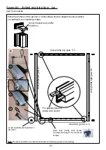
Page 20: ...to pos 5 8 with pan head screw 3 5 x 38 S6 Assembly divided revolving door bottom view from outside square tube pos 5 8 door profile top pos 5 9 sash lock V28 with screw countersunk head 3 5 x 22 S 9 scews door profile right pos 5 7 door profile left pos 5 6 glazing block V32 screw counter sunk head 4 2 x 45 S 7 door profile bottom pos 5 3 1 Note The seal is bundled in one strand for all doors and...

Page 21: ...r locking device 1 1 S22 wing type self drill screw counters head 3 5 x 13 door stop 1 1 V30 V31 corner bracket door profil 2 2 20 Profiles for divided revolving door top Note The seal is bundled in one strand or all doors and windows please cut accordingly Content accessories bag divided revolving door top left item no 9999 0009 right item no 9999 0011 outside item no 9999 0035 inside item no 999...

Page 22: ...bracket door profile V30 V3 Assembly of door handle door profile top pos 5 3 door profile right pos 5 2 door profile left pos 5 1 Fix glazing block in place with silicon cross bar pos 5 4 1 sash lock V28 with screw countersunk head 3 5 x 22 S 9 screws screw countersunk head 4 2 x 45 S 7 Note The seal is bundled in one strand for all doors and windows please cut accordingly 1 2 3 4 ...

Page 23: ...h Placement Riga Model IIs IIIs IVs Door Catch Placement Riga Model III IV V Installation of Door Catch Edge Curve Handle with Screw Cap 3 5 x 13mm Screw 3 5 x 13mm Screw Crossbar Crossbar Handle without Screw Cap ...

Page 24: ...dow 1 1 V145 corner fixation of window 1 1 S9 screw pan head 4 2 x 3 2 2 V30 V31 corner bracket door profil 2 2 S12 S1 hexagonal screw M6 x 12 with nut M6 4 4 23 Profiles for rear window Content accessories bag rear window Note The seal is bundled in one strand for all doors and windows please cut accordingly item no 9999 0160 item no 9999 0358 item no 9999 0163 item no 9999 0023 item no 9999 0152...

Page 25: ... S19 screws Screw countersunk head 4 2 x 45 S 7 cross bar pos 5 4 2 Hole location on inside for opener for rear window If you are in a high wind area install closer to the middle opener with screw pan head 4 2 x 3 S9 screw Note The seal is bundled in one strand for all doors and windows please cut accordingly The required mounting bracket is placed on the preinserted M6 x 6 S5 bolts and screwed wi...

Page 26: ...h pan head screws 4 2 x 13 S9 to step 10 step 8 step 9 step 10 ATTENTION When using a foundation frame attach it to the soil profile before these steps see pages 5 6 ridge profile pos 3 3 at the gable and end plate V screw with screw pan head 4 2 x 3 S9 ridge profil pos 3 3 Support end or hold it up insert the side glazing and slide into the edge curve First attach the soil profiles pos 2 1 to the...

Page 27: ...rubber mallet on the side curve to move it down Be careful not to damage the aluminum Tip A light grease on the plastic sliders may help movement to step 11 Continue inserting the side glazing and side curves The connecting plate V4 is attached from the inside with screw hex M6 x 16 and nut M6 This secures the window crossbar to the greenhouse to step 12 step 11 Assembly procedure eaves ATTENTION ...

Page 28: ...nting roof window wrong right The stabilization angle pos 3 4 is installed on both sides from inside It is attached to the side curve with screw M6 x 16 nut M6 and washer A6 4 screwed The stabilization angles pos 3 4 are also the rear supports for the top and bottom shelf see separate instructions Glazing cut away in image to show installation Assembly procedure eaves ATTENTION When using a founda...

Page 29: ... 30 11 16 x 9 7 16 2 779 x 239 mm 30 11 16 x 9 7 16 2 724 x 1031 mm 28 1 2 x 40 9 16 2 724 x 1031 mm 28 1 2 x 40 9 16 2 724 x 1031 mm 28 1 2 x 40 9 16 2 724 x 1215 mm 28 1 2 x 47 13 16 2 724 x 1215 mm 28 1 2 x 47 13 16 2 724 x 1215 mm 28 1 2 x 47 13 16 1 724 x 676 mm 28 1 2 x 26 5 8 1 724 x 676 mm 28 1 2 x 26 5 8 1 724 x 676 mm 28 1 2 x 26 5 8 1 724 x 676 mm 28 1 2 x 26 5 8 1 724 x 676 mm 28 1 2 x...

Page 30: ... 5 6 strut Ø20 x 1 5 32 inches V36 angle end tail narrow 6 8 10 12 5 3 4 5 6 cross brace V161 2 2 4 6 connector with grub screw 2 3 hexagonal screw M6 x 12 with nut M6 S12 S1 3 4 5 6 hexagonal screw M6 x 16 with nut M6 S5 S1 3 4 5 6 T head bolt M6 x 16 with nut M6 S15 S1 3 4 5 6 Allen key V21 1 1 1 1 Polycarbonate sheets shelf surface In a separate box 2 3 4 5 29 ...

Page 31: ...longitudinal profile II Riga III Riga V 1x 2104 mm 82 8 inches 1x 3162 mm 124 5 inches 1x 4220 mm 166 1 inches 1x 5278 mm 207 8 inches The sections of longitudinal profiles pos 1 are connected with connectors with grub screws V161 as shown to the left Tighten the set screws grub screws with included Allen wrench greenhouse curve Pos 3 Pos 1 Pos 5 Assembly Overview Riga Riga IV 30 ...

Page 32: ...S12 per greenhouse rung In the lower channel on the outside of the longitudinal profile pos 1 pull per greenhouse run a bolt M6 x 16 S5 from the end one 31 In the lower channel on the greenhouse lateral support insert one M6 x 12 S12 per inner curve of the greenhouse In lower channel on the outside of the shelf longitudinal profile pos 1 insert one bolt M6 x 16 S5 per inner curve Insert one M6 x 1...

Page 33: ...entermost curve attach crossbrace to bolt in longitudinal profile pos 1 then install strut assembly beneath and tighten with nut Repeat at all inner curves Use the T head bolts S15 to attach angle pos 6 to greenhouse gable crossbar 32 To bolt the struts to the inner curves insert bolt S5 at the insertion point on black plastic foot of the curve Attach strut with nut S1 Finally insert the polycarbo...

Page 34: ...4 strut Ø20 x 1 5 18 inches V36 angle end tail narrow 2 4 6 8 5 1 2 3 4 cross brace angle 6 2 2 2 2 V161 2 2 4 6 connector with grub screw 2 3 hexagonal screw M6 x 12 with nut M6 Shorter screw S12 S1 7 8 9 10 hexagonal screw M6 x 16 with nut M6 Longer screw S5 S1 2 4 6 8 T head bolt M6 x 16 with nut M6 S15 S1 2 2 2 2 Allen key V21 1 1 1 1 33 Polycarbonate sheets shelf surface In a separate box 2 3...

Page 35: ...gitudinal profile II Riga III Riga V 1x 2104 mm 82 8 inches 1x 3162 mm 124 5 inches 1x 4220 mm 166 1 inches 1x 5278 mm 207 8 inches The sections of longitudinal profiles pos 1 are connected with connectors with grub screws V161 as shown to the left Tighten the set screws grub screws with included Allen wrench greenhouse curve Pos 3 Pos 1 Pos 5 Assembly Overview Riga Riga IV 34 ...

Page 36: ...side channel of the lateral support as shown in picture Lay the cross profile pos 2 on top of the greenhouse lateral support and attach with supplied nuts pos S1 35 In the lower channel on the greenhouse lateral support insert one M6 x 12 S12 per inner curve of the greenhouse In lower channel on the outside of the shelf longitudinal profile pos 1 insert one bolt M6 x 16 S5 per inner curve Insert o...

Page 37: ...e attach crossbrace to bolt in longitudinal profile pos 1 then install strut assembly beneath and tighten with nut Repeat at all inner curves Use the T head bolts S15 to attach angle pos 6 to greenhouse gable crossbar 36 To bolt the struts to the inner curves insert bolt S5 at the insertion point on black plastic foot of the curve Attach strut with nut S1 Finally insert the polycarbonate panels St...

Page 38: ... of the cross bar to support the weight as seen below For the Riga XL the best placement is above the rear wall door with the weight on the door frame as seen to the left You may cut the hole in the polycarbonate before or after assembly of the greenhouse Draw the outline of hole to be cut only the area protruding from the polycarbonate Drill a hole in each corner of the panel to insert a fine too...

Page 39: ...along your marked lines note if you use this method your measurement will be different than the ones to the right Step 2 Bolt the heavy thick L bracket which comes with the vent to the galvanized steel T bracket supplied by us screw self tapping screws the T bracket to the bottom of the vent and cross bar slightly off center You may want to drill small pilot holes Attach the motor to the L bracket...

Page 40: ...ssembly Questions Give us a call Toll free 1 877 760 8500 customerservice exaco com Exaco Trading www EXACO com Please watch our animated assembly video on our Exaco Trading Co YouTube Channel Find the link at www exaco com ...

Reviews: