BA_PH_245-20_EN_15-22.docx
26
7
Installation
and Connection
7.1
Check Delivery Conditions
Check the consignment for completeness and possible transport damage. In case of transport damage, please
keep the packaging and inform the shipping company and the manufacturer immediately! Later complaints can-
not be accepted.
7.2
Transport to the Installation Site
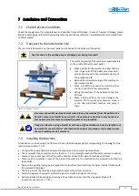
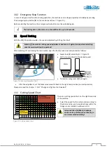
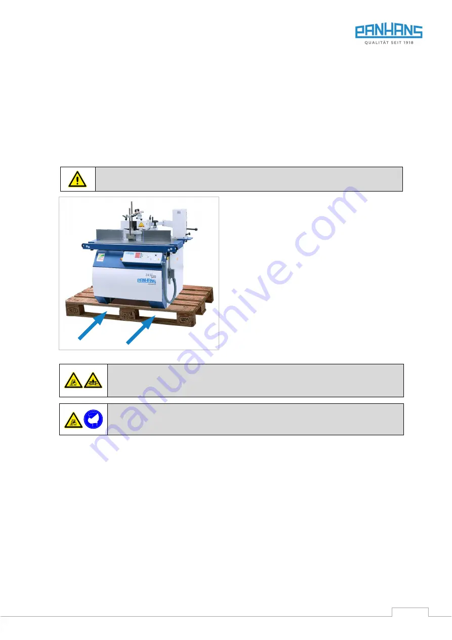
The machine is delivered on a transport pallet and is bolted to the bottom of the pallet.
Pay attention to the existing danger of tipping over during transport!
Figure 6: Transport pallet
The centre of gravity of the machine is approximately
in the middle of the transport pallet.
•
Move a pallet truck between the pallet timbers
(see
Figure 6), lift the pallet only a few centi-
metres and move it to the immediate vicinity of
the installation site.
•
Remove the screw fastenings of the machine on
the transport pallet.
•
Move a forklift truck under the machine from
the front and lift it a few centimetres.
•
Lifting the machine off the pallet with the fork-
lift truck.
•
Move a lift truck from the front between the
machine, lift it only a few centimetres, move it
to the final installation location and place it
there.
Be aware of possible crushing hazards when placing the machine (from the pallet to the
floor) by means of a forklift truck or similar. Pay particular attention to your hands and
feet and wear safety shoes and protective gloves as a precaution.
Danger to life when using a forklift truck! Keep a sufficient distance from the forklift truck
and watch its speed. Vehicles with combustion engines also produce toxic exhaust gases.
Wear a breathing mask if necessary.
7.3
Installing the Machine
A foundation is not required. The floor must have a load-bearing capacity corresponding to the weight of the
machine (see section
•
Unscrew the square timbers and place the machine on a horizontal workshop floor.
•
The net weight of your machine can be found in
5.1 (net weight means without accessories or options).
•
Level out any unevenness of the floor with underlays and with the aid of a machine spirit level.
•
There is a Ø 14 mm hole on each of the 4 feet of the machine. The machine can be screwed to the floor via
these holes.
•
Remove the existing lashing points (eyebolts) for truck transport and close the open internal threads with
the enclosed blind plugs.
•
The bare parts of the machine are greased to protect them from corrosion.
•
Carefully degrease these parts protected against rust with petroleum or benzine.
•
Activate lubricant dispensing by screwing in the activation screw until the ring eyelet breaks off
(procedure see section


