BA_PH_245-20_EN_15-22.docx
37
13
Positioning the Spindle Height and Tilt
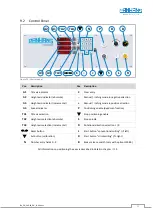
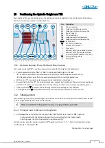
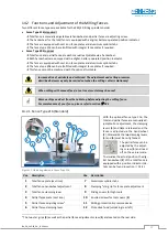
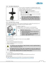
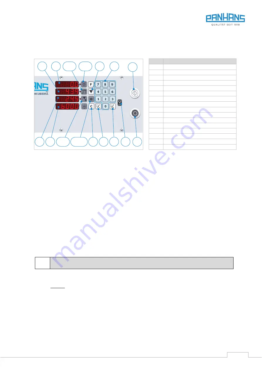
The height and tilt axes are positioned via the positioning control integrated in the control panel. All positions
and the set speed are visualised via LED indicators.
Figure 22: Operating elements of the positioning control
Pos. Description
A1
Tilt axis indicator
A2
Height axis indicator (absolute)
A3
Height axis indicator (incremental)
A4
Speed indicator
TA1
Tilt axis selection
TA2
Height axis selection (absolute)
TA3
Height axis selection (incremental)
0
Reset button
Set button (calibration)
N
Number entry fields 0 - 9
C
Clear entry
–
Manual / inching in negative direction
+
Manual / inching in positive direction
P
Positioning enable (deadman function)
Stop positioning enable
S
Stop spindle
13.1
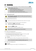
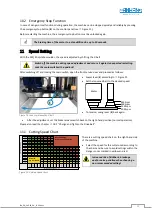
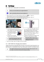
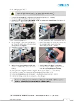
Activate Number Entry Field and Enter Values
The
number entry field “
N
” is used to enter position values for the height or tilt adjustment
.
•
Press the selection button “
TA1
” or “
TA2
” in the desired field (height or tilt axis)
→
The number entry field is activated when the LED next to the axis selection button is lit up.
→
All target position values that are now entered apply to the currently activated axis.
•
With button “
C
”, incorrectly entered values can be deleted and entered again.
•
By pressing the button “
P
”, the entered values are accepted and
positioned. The axes are only positioned
while the “
P
” button is pressed (deadman function). As soon as the button is released, positioning stops.
•
If the stop button
is pressed, the positioning stops and the existing value is adopted.
•
Pressing the button
at standstill deactivates the entry field and deletes any values entered.
13.2
Tilt Adjustment
The positioning of the milling spindle angle is done either in manual resp. inching mode or continuously by prior
entry of target values via the number entry field
“
N
”
.
Please note: With the milling spindle running, no angle positioning is possible!
13.2.1
Tilt Adjustment in Manual or Inching Mode
•
First activate the entry field for the tilt axis via the
“
TA1
”
button
→
LED next to
“
TA1
”
lights up.
-
In manual mode, the tilt can be positioned continuously, directly to the desired angle.
-
In inching mode, the tilt can be adjusted in single steps of 0.1°.
For both modes, press the positioning button “
P
” together with the “
+
” or “
–
“ button and read the position
simultaneously in the display “
A1
”.
Continuation
see next page
P
S
A1
A2
A4
A3
TA3
"
0
!
TA2
TA1
N
C
–
+

