BA_PH_245-20_EN_15-22.docx
38
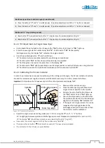
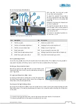
Continuously position to desired angle (manual mode):
a)
Press the buttons “
P
” and “
+
” simultaneously
→
positive adjustment until the “
+
” button is released
b)
Press the buttons “
P
” and “
–
” simultaneously
→
positive adjustment until the “
–
” button is released
Position in 0.1° steps (inching mode):
a)
Keep button “
P
” pressed and tap button “
+
” step by step
→
positive adjustment by 0.1°
b)
Keep button “
P
” pressed and tap button “
–
” step by step
→
positive adjustment by 0.1°
13.2.2
Tilt Adjustment via Target Value Input
•
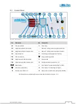
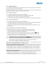
First activate the entry field for the tilt axis via the
“
TA1
”
button
→
LED next to
“
TA1
”
lights up.
•
Enter the new angle via the number entry field
“
N
”
→
LED next to
“
TA1
”
flashes quickly.
(during value entry, the display
“
A1
”
indicates the angle entered).
•
Press the positioning button
“
P
”
and hold it down:
→
The entered value is accepted, enabled for positioning and positioned
→
The LED next to
“
TA1
”
flashes slowly until positioning is completed
→
The tilt angle can be read at the same time in the display
“
A1
”
→
The LED next to
“
TA1
”
lights up statically once the target position is reached (actual value = target value)
→
The still active axis can be repositioned immediately via the number entry fields
“
N
”
13.2.3
Calibrating the Tilt Axis Indicator
In order to permanently ensure exact positioning of the milling spindle angle, the tilt axis indicator should be
checked for correctness at regular intervals and calibrated if necessary. To do this, proceed as follows:
Important:
First position the tilt axis exactly to 0.0° via tilt adjustment and display
“
A1
”
.
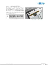
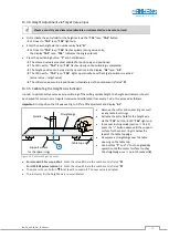
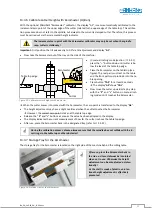
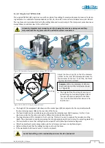
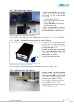
Figure 23: Calibrate tilt indicator
•
Remove cutter and spacer rings.
•
Close the table opening with table insert
rings as close as possible to the spindle.
•
Activate the entry field for the tilt axis via
the
“
TA1
”
button
→
LED
“
TA1
”
lights up.
•
Use a knife-edge square to check whether
the spindle is exactly at 90° to the table top
edge when the display
“
A1
”
indicates 0.0°.
•
If the angle is no longer correct, this can be
recognised by a light gap between the
knife-edge square and the spindle
→
Then
the indicator must be calibrated.
•
Adjust the angle in manual inching mode (see
13.2.1) using the
“
P
”
and
“
–
“
/
”
+
”
buttons.
→
The light gap between spindle and knife-edge square must disappear completely (90°
≙
position 0.0°).
→
The display
“
A1
”
should now indicate a value deviating from 0.0° (e.g. 0.6°).
•
Now enter the correct angle of 0.0° via the number entry field “
N
”
.
•
Then press the set button
for at least 3 seconds
→
The new value is adopted.
•
The indicator for the tilt axis is now calibrated.
Knife-edge square
Table top edge
Spindle
Table insert rings

