BA_PH_436-100_EN_44-21.docx
46
Step 5
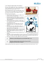
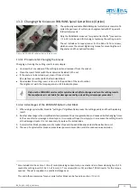
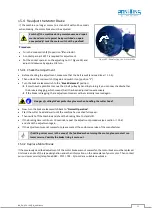
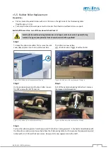
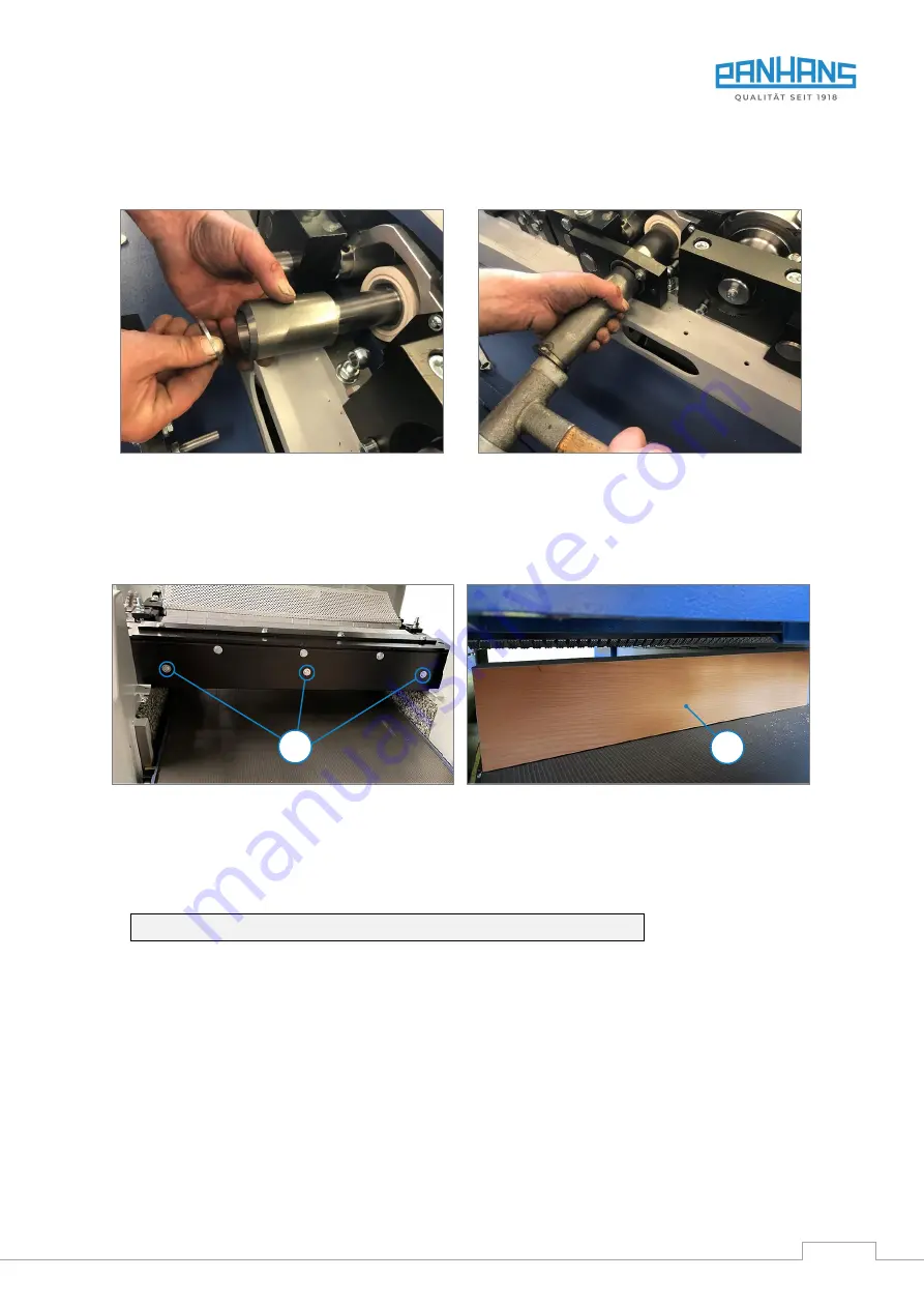
Place the sleeve and the shim washer and push them in. Important: The black sealing ring must be fitted
properly. Use a press-in tube or a piece of wood and a rubber mallet to carefully tap the pendulum bearing
inwards. Then tighten with the M8 screw (SW 13) and washer.
Figure 57: Rubber roller replacement Step 5a
Figure 58: Rubber roller replacement Step 5b
The outfeed rollers are then also replaced in the same way.
15.6
Adjustment of the Anti-Kickback Fingers
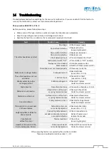
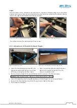
Figure 59: Adjusting screws
•
Loosen the three M6 adjusting screws (
E
) in the
oblong holes with an SW10 spanner, push them
all the way up and lightly tack them in place.
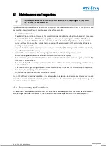
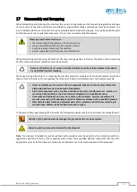
Figure 60: Dressed squared timber as adjusting aid
•
Dress a square timber (
K
) with a length of approx.
620 mm and a height of at least 150 mm. This
serves as an adjustment aid.
•
Measure the actual height of the squared timber and set 2 mm more on the thickness planer.
Example:
Height squared timber = 200 mm | Setting thickness planer = 202 mm
•
Loosen the tacked adjustment screws (
E
) and make sure that all fingers rest on the squared timber.
•
Now push the three adjusting screws (
E
) all the way down and tighten them again.
•
The procedure is completed.
E
K

