BA_PH_436-100_EN_44-21.docx
27
8.2
Control Panel (Details)
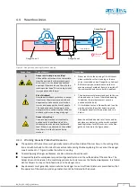
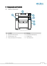
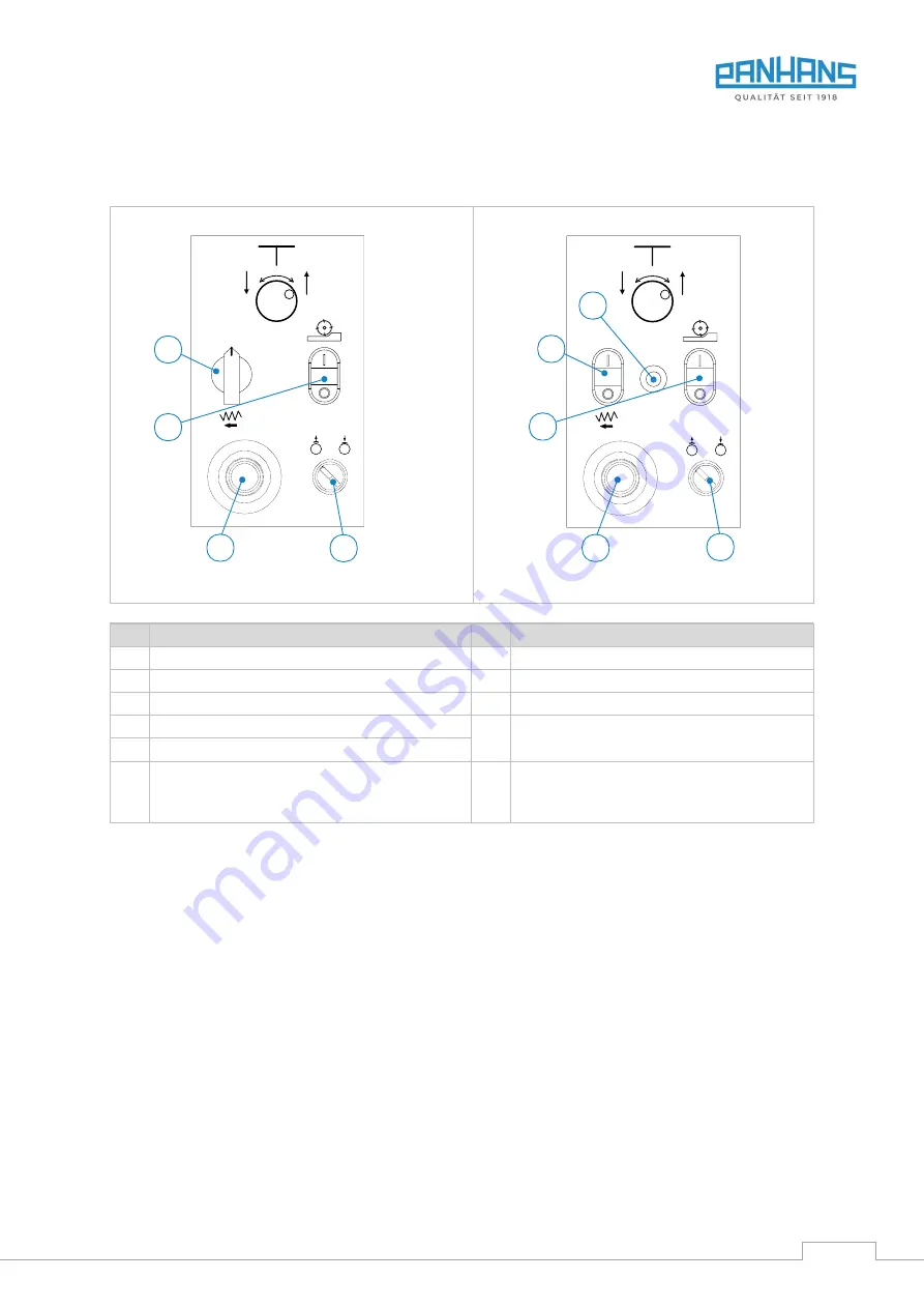
This section shows a detailed view of the control panel (
1
) shown in
Figure 11 with the existing switches and
controls, which vary in the standard and optional equipment.
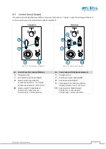
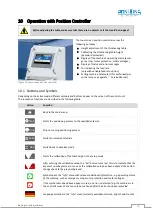
Figure 12: Control panel (standard)
Figure 13: Control panel (option)
No. Control Panel for Standard Machine
No. Control panel with Optional Equipment
5
Emergency stop
5
Emergency stop
7
Push button cutter head ON/OFF
7
Push button cutter head ON/OFF
8
Selector switch feed ON/OFF
8
Push button feed ON/OFF
a) Feed rate position
I
→
7 m/min
9
Potentiometer for feed rate (option),
infinitely variable from 3 - 24 m/min
b) Feed rate position
II
→
14 m/min
10
Selector switch
“Brake Release”
Position left = brake released
Position right = normal operation
10
Selector switch
“Brake Release”
Position left = brake released
Position right = normal operation
0 I II
8
Standard
7
10
5
0 II
1
2
3
4
5
0
.
.
.
.
.
.
Optional
8
9
7
5
10


