background image


BA_PH_436-100_EN_44-21.docx


36


11


Fine adjustable Table Rollers 

(Option) 

When equipped with this option, two adjustable table rollers are built into the thicknessing table for better 
sliding of the wood. 

11.1


Adjusting the Table Rollers


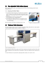
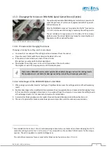
The knurled thumbwheel (see figure on the right) is used to adjust the 
rollers according to the condition of the wood. The adjustment range is 
approx. 1 mm. The planing result deteriorates the higher the table roll-
ers are set. 


With full stop left, the rollers are in lowest position 

 Use this setting on dry, well-dressed wood. 


With full stop on the right, the rollers are in the uppermost position 

 Use this setting on damp, resin-rich or non-straightened wood to  

      ensure safe feeding. 

 
The article number of this option can be found in section 

 16.2. 


Figure 40: Adjusting the table rollers 

12


Thickness Table Extensions 

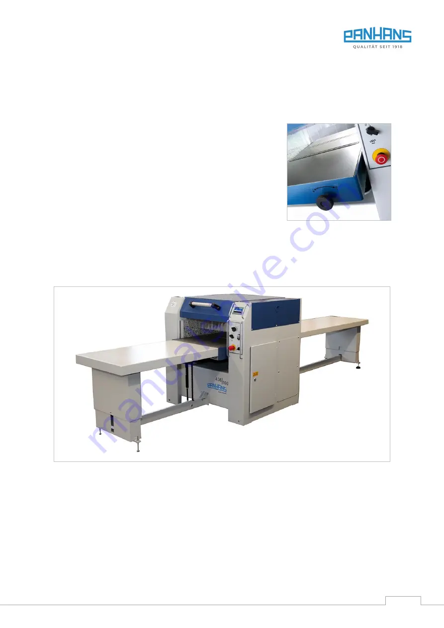
For machining long workpieces, the use of the optionally available thickness table extensions is recommended. 
These are available in lengths of 400 mm, 1000 mm and 2000 mm.  


Figure 41: Optional table extensions 

When attaching the table extensions, make sure that they are aligned on all sides with a spirit level to the correct 
height and parallelism to the machine table. The adjustment is made via the adjustment screws attached to the 
feet.   

For more information on the option and corresponding article numbers, refer to section 

 16.2. 


Summary of Contents for PANHANS 436/100

Page 1: ...MA Maschinenbau GmbH Graf Stauffenberg Kaserne Binger Str 28 Halle 120 DE 72488 Sigmaringen Tel 49 07571 755 0 E Mail info hokubema panhans de Web https hokubema panhans de Operating Manual Thickness Planer PANHANS 436 100 Machine Type 436 100 ...

Page 2: ... Use 12 4 1 2 Modifications and Conversions to the Machine 12 4 1 3 Residual Risks 13 4 2 Observe the Environmental Protection Regulations 14 4 2 1 Organisational Measures 14 4 2 2 Personnel Selection and Qualification Basic Duties 14 4 3 Safety Instructions for Specific Phases of Operation 15 4 3 1 Normal Operation 15 4 3 2 Special work within the Scope of Maintenance Work as well as Troubleshoot...

Page 3: ...vating the Controller 30 10 3 Operating States Language Info Menu 30 10 4 Positioning Mode Machine Menu 31 10 4 1 Table Height Positioning in Absolute Mode 31 10 4 2 Table Height Positioning in Incremental Mode 31 10 5 Calibrating the Table Height Setup Menu 32 10 6 Feed Rate Visualisation Option 32 10 7 Warnings and Error Messages 33 10 7 1 Warnings 33 10 7 2 Error Messages 34 11 Fine adjustable ...

Page 4: ...ion 47 16 1 3 Accessories for Spiral Cutter Block Option 47 16 2 Optional Table Systems 48 16 3 Special Accessories 48 17 Disassembly and Scrapping 49 EU Declaration of Conformity 50 List of Figures Figure 1 Thickness planer 436 100 6 Figure 2 Danger zones during thickness planing 17 Figure 3 Nameplate 18 Figure 4 Working areas top view 19 Figure 5 Dimensions side view and top view 20 Figure 6 Dim...

Page 5: ...e extensions 36 Figure 42 Making the cutter block accessible 37 Figure 43 Changing Tersa knives 37 Figure 44 Traditional cutter block 38 Figure 45 Standard adjusting devices 38 Figure 46 Magnetic quick adjusters 1533 39 Figure 47 Adjustment of the cutter head 39 Figure 48 PANHANS spiral cutter carbide inserts 40 Figure 49 Grease nipples for adjusting spindles 43 Figure 50 Grease lateral guides 43 ...

Page 6: ...nance during maintenance servicing inspection repair and or during transport Apart from the operating manual and the legally binding accident prevention provisions applicable in the country and place of use the recognized technical regulations for safe and proper work must also be observed 1 1 Legal Notice All contents of these operating instructions are subject to the rights of use and copyright ...

Page 7: ... these instructions may result in personal injury Reference to the obligation to wear protective goggles Non observance of these instructions may result in personal injury Reference to the obligation to wear a respiratory protection mask Non observance of these instructions may cause breathing difficulties and lung damage Possible dangerous crushing hazard in the area of stationary objects Risk of...

Page 8: ...the operator must ensure the following measures Product training for every operator also possible external personnel Regular safety instruction 3 2 Requirements for the Operators The thickness planer may only be operated by trained personnel who have also read this manual Inspection maintenance cleaning and repair may only be performed by technical specialists with product specific training and me...

Page 9: ...ay and repaired if necessary For repairs only original spare parts may be used All protective safety and monitoring devices must be regularly checked and maintained by the operator Only instructed trained or qualified persons may work on this machine Maintenance work must be carried out and documented in accordance with the maintenance instruc tions After maintenance or repair the machine may only...

Page 10: ... with mechanical motor brake It has a central circuit with push button and motor protection switch All operating elements and switches are mounted on the front and are therefore easily accessible The main switch is at the rear of the machine and also serves as emergency stop The protective devices comply with the regulations of the German Employer s Liability Insurance Associa tion for Wood 3 6 Ad...

Page 11: ...on 16 2 Steel feed roller spiral toothed instead of rubber feed roller see section 16 2 Steel link feed roller pendulum mounted for simultaneous planing of mouldings with max 3 mm thickness tolerance Table extension 400 mm mounted on the machine table in the outfeed area see section 16 2 Thickness table extension L 1000 mm B 630 mm with automatic height adjustment see section 16 2 Thickness table ...

Page 12: ...d approval of the manufacturer Improper use can lead to danger to persons and to a defect or damage to the machine Only the manufacturer s original planing cutter blocks and replacement knifes according to EN 847 1 are permitted as tools These must be marked with MAN Processing type Length Height Width Thickness planing 5500 mm 3 300 mm 630 mm The machine is not suitable for operation outdoors or ...

Page 13: ... safety shoes especially when transporting and setting down the machine Pay attention to the existing danger of cuts on the planing knifes Never reach into the running band saw blade Wear protective gloves when changing the planing knifes Be aware of the danger of cuts due to chips and splinters and never remove them from the danger area by hand Be aware of a possible danger of being drawn in by m...

Page 14: ...ng manual Operators must not wear open long hair loose clothing or jewellery including rings There is a risk of in jury e g by getting caught or drawn in Observe the safety instructions and danger warnings on the machine and keep them complete and in legi ble condition In case of safety relevant changes to the machine or its operating behaviour shut down the entire system immediately and report th...

Page 15: ...visible damage and defects at least once per shift Any changes that have occurred including those in the operating behaviour must be reported immedi ately to the responsible office or person If necessary stop and secure the machine immediately Extraction The machine must be connected to an effective extraction system This requires a mean flow velocity of 20 m s Work area An obstacle free work area...

Page 16: ...tely after completion of the maintenance and repair work Ensure safe and environmentally friendly disposal of operating and auxiliary materials e g oils and re placement parts e g electronic components 4 3 3 Safe Working Practices Always work with all protective devices These must be in the intended places and in perfect working or der Defective guards must be replaced immediately Do not start pla...

Page 17: ...hen the cutter head is running This applies equally to the operator and to a helper 3 Danger of crushing The processed workpiece is constantly pushed out of the outfeed side of the thickness planer by means of automatic feed If there is an obstacle on the outfeed side there is a risk of a person being crushed Keep the outfeed side clear at all times and do not place any obstacles such as walls mat...

Page 18: ...on outlet Ø 160 mm Manufacturer HOKUBEMA Maschinenbau GmbH Graf Stauffenberg Kaserne Binger Str 28 Halle 120 DE 72488 Sigmaringen Germany Tel 49 0 7571 755 0 Fax 49 0 7571 755 2 22 Figure 3 Nameplate 5 2 Technical Features 1040 mm long machine table with finely planed cast iron surface and the typical features of the proven PANHANS thickness planers Suction nozzle for optimum extraction Pendulum m...

Page 19: ...lso vary from country to country However this information should enable the user to make a better assessment of hazard and risk 5 3 2 Noise Emission Values The specified measured values are determined in accordance with EN 860 Uncertainty allowance K 4 dB A Workplace related emission value Sound power level Idle Working area 1 74 0 dB A Idle Lwa 83 4 dB A Working area 2 70 6 dB A Working Working a...

Page 20: ...BA_PH_436 100_EN_44 21 docx 20 6 Dimensions 6 1 Side View and Top View Figure 5 Dimensions side view and top view Subject to design and dimensional changes 1114 1091 1191 2110 1110 ...

Page 21: ...BA_PH_436 100_EN_44 21 docx 21 6 2 Front View Figure 6 Dimensions front view Subject to design and dimensional changes 185 185 ...

Page 22: ...g transport Figure 7 Transportation 7 3 Installing the Machine A foundation is not required The floor must have a load bearing capacity corresponding to the machine weight 1050 kg Level out any unevenness of the floor with underlays and a spirit level The bare parts of the machine are greased to protect them from corrosion Carefully degrease the parts protected against rust with petroleum or benzi...

Page 23: ...he pallet must also be secured against slipping Please note the following when lashing in the transport vehicle The loading area of the transport vehicle must always be clean and dry The lashing straps used must be suitable for the total weight of the machine approx 1050 kg Fastening on the loading area is done by lashing down This means that the transport pallet is secured by frictional locking T...

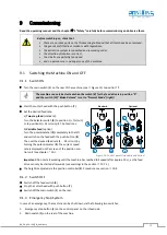
Page 24: ...13 and 14 of contactor Q2 Installation only by a qualified electrician The air speed must be set in such a way that with the extraction line connected and the tools stationary an average air speed of 20 m s 1450 m h for dry chips 28 m s 2050 m h with moist chips moisture 18 or more is achieved at the extraction nozzles Required negative pressure at 20 m s 600 Pa If the machine is properly connecte...

Page 25: ...ust tight Observe the direction of rotation of the cutter head as well as the move ment direction of the feed Figure 10 Control cabinet If the direction of rotation of the cutter resp the movement direction of the feed is not correct two outer conductors must be swapped at the corresponding motor connection The cover may not be open Risk of injury from rotating parts Only if the connection is carr...

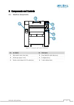
Page 26: ...Components Figure 11 Components and controls front view No Description No Description 1 Main switch rear of machine 4 Bow handle for protective cover 2 Control panel see 8 2 5 Emergency stop 3 Position controller with 4 3 touchscreen 6 Control cabinet door C 1 2 3 6 4 5 ...

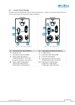
Page 27: ...al Equipment 5 Emergency stop 5 Emergency stop 7 Push button cutter head ON OFF 7 Push button cutter head ON OFF 8 Selector switch feed ON OFF 8 Push button feed ON OFF a Feed rate position I 7 m min 9 Potentiometer for feed rate option infinitely variable from 3 24 m min b Feed rate position II 14 m min 10 Selector switch Brake Release Position left brake released Position right normal operation ...

Page 28: ...the Selector switch 8 to position I 7 m min or to position II 14 m min The feed runs b Variable feed option Turn the potentiometer 9 completely to the left and switch on the feed with the push button 8 Then set the desired feed rate 3 24 m min by turning the potentiometer 9 The current speed rate is displayed on the screen of the position con trol unit see chapter 10 Figure 14 Control panels stand...

Page 29: ...l unit The respective functions are described in the following table Action Function Back to the main menu Starts the positioning process to the specified setpoint Stops a running positioning process Switch to incremental mode Switch back to absolute mode Starts the calibration of the table height in the setup mode After entering the calibration value the Set button turns red This is to indicate t...

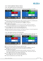
Page 30: ... 10 3 Operating States Language Info Menu By tapping the symbol resp you can access the Info menu Various operating states the machine and version number the year of manufacture and various messages are displayed here In addition the menu lan guage German English or French for the control system can be set here Figure 18 Info menu with status messages Figure 19 Language menu Status messages exampl...

Page 31: ... value this is first overrun by approx 1 mm and then approached from below This serves to compensate for spindle play loop function 10 4 2 Table Height Positioning in Incremental Mode In this mode positioning is incremental resp at each Start the dimension entered in the Set field is sub tracted from the current actual value Thus the incremental value defines the depth of cut max 8 mm Figure 22 Se...

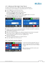
Page 32: ...nce value Now use a test workpiece that has already been dressed and set the table to any height that is suitable for a thickness planing test run with the selected test workpiece Start the thickness planing test run Measure the machined test workpiece with a suitable measuring device vernier caliper recommended Enter the measured value z B 101 3 mm into the Cal Value field see Figure 25 The Set b...

Page 33: ...tective cover Remedy Close the protective cover Figure 28 Warning 2 Cause The feed switch is in position I ON The feed can only be switched on when the cutter head has reached full speed and the start stop button stops flashing Remedy Switch off the feed switch Figure 29 Warning 3 Cause The machine brakes Remedy Please wait until the machine has stopped completely Figure 30 Warning 4 Cause The Bra...

Page 34: ...Fault on the motor protection of the feed motor1 Remedy Check the motor circuit breaker and if necessary the existing fuses and connections Figure 34 Error message4 Cause The thermal fuse WSK has tripped because the motor has become too hot Remedy Allow the machine to cool down and then switch on again In case of repeated occurrence contact customer service Figure 35 Error message5 Cause The thick...

Page 35: ...urrent was exceeded a The thickness table was moved against block b Spindle guide is too sluggish c Thickness table extension runs sluggishly Remedy a Release blockade b Clean and grease spindle guide c Check the table extension mechanically Figure 39 Error message9 Cause Abrupt increase in current The positioning was stopped because the dl t monitoring has triggered The thickness table was moved ...

Page 36: ...the rollers are in the uppermost position Use this setting on damp resin rich or non straightened wood to ensure safe feeding The article number of this option can be found in section 16 2 Figure 40 Adjusting the table rollers 12 Thickness Table Extensions For machining long workpieces the use of the optionally available thickness table extensions is recommended These are available in lengths of 4...

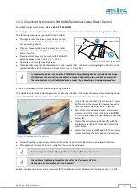
Page 37: ...ary cuts from the knives are possible Always wear protective gloves when changing the knives 13 1 Changing the TERSA Knives on an All Steel Cutter Block standard Only use original replacement planing knives from the manufacturer The blades must always be the same length as the maximum planer width 630 mm with 436 100 Knock back the pressure bar segments using a hammer in combina tion with the bras...

Page 38: ...e caused by a deviating or improper procedure 13 2 1 PANHANS Cutter Block Adjusting Devices The standard cutter block adjusting devices are already included in the scope of delivery when ordering the op tional PANHANS traditional cutter block The correct adjustment is carried out as described below Figure 45 Standard adjusting devices Using a flat spanner SW17 as shown in Figure 45 loosen all the ...

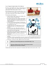
Page 39: ...1 0 mm The adjusting nut 2 is to be turned back by 10 pitch points 3 Then insert the new resp sharpened knives 1 press them into the knife holder of the cutter head with a piece of wood and screw them slightly tight After adjustment of the adjusters they are placed over the planing knives according to Figure 47 so that the spring loaded pin 6 rests against the cutter body clamping screw side The k...

Page 40: ...panner until it locks into place Only use the PANHANS service set for spiral cutter shafts to change and turn the cutting inserts The manufacturer is not liable for damage caused by a deviating or improper procedure 13 3 2 Advantages of the PANHANS Spiral Cutter Block 1 When using a spiral cutter block its pulling cut significantly improves the cutting quality and thus the planing result 2 Another...

Page 41: ...15 3 The cutter head does not run up cleanly V belt too loose Tension the V belt see section 15 3 Rubber extension rollers no longer pull out Rubber coating worn Readjust replace Contact customer service Feed unevenly Drive chain too loose Tension the chain see 15 1 Material is not drawn in Infeed roller is set too high or spring tension too low Readjust infeed roller Contact customer service Mate...

Page 42: ...trician if necessary Immediately remove and replace damaged guards Never work with damaged equipment Before starting work check the extraction system for full function every day The extraction system must be checked for obvious defects before initial commissioning daily and monthly to ensure its effectiveness The air velocity to the extraction system must be checked before the initial commissionin...

Page 43: ... a suitable grease Move the thicknessing table upwards every month and lubricate the 4 adjusting spindles N with 2 grease shots each Figure 49 Lightly grease the two lateral guides F on the thicknessing table front and back every month Figure 50 Figure 50 Grease lateral guides 15 3 Replace Tension the V belt Switch off the machine during maintenance and repair work and secure it against being swit...

Page 44: ...rake is dragging which means that it has been adjusted too excessively If the brake is dragging the readjustment made must be minimally reversed again Danger of cutting Wear protective gloves when handling the cutter head Now turn the brake release switch back to Normal Operation Start the cutter head and wait until the machine has reached full speed Then switch off the machine and check the braki...

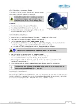
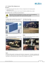
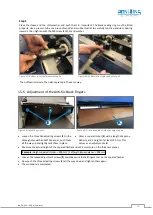
Page 45: ... and place it on the top of the machine The rollers are now visible Left infeed roller Right outfeed roller Figure 53 Rubber roller replacement Step 1a Figure 54 Rubber roller replacement Step 1b Step 2 Step 3 On the pendulum bearing of the feed roller loosen the M8 screw with a SW13 spanner Pull off the pendulum bearing to the front remove the sleeve and shim washer Figure 55 Rubber roller replac...

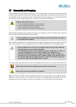
Page 46: ...Figure 59 Adjusting screws Loosen the three M6 adjusting screws E in the oblong holes with an SW10 spanner push them all the way up and lightly tack them in place Figure 60 Dressed squared timber as adjusting aid Dress a square timber K with a length of approx 620 mm and a height of at least 150 mm This serves as an adjustment aid Measure the actual height of the squared timber and set 2 mm more o...

Page 47: ...rs 4131 Cutter Block Spare Screws Standard version height approx 21 mm hardened R 1 4 SW 17 4107 Flat Spanner SW17 For cutter head screws with spanner size 17 mm 4113 Cutter Block Pressure Spring For lifting the knives and for easier adjustment of the knives with mag netic quick adjusters see Art No 2004 above 4114 16 1 3 Accessories for Spiral Cutter Block Option Article Description Art No Solid ...

Page 48: ...nce of 3 0 mm Table glide rollers absolutely necessary 4484 Frequency controlled Feed Motor Infinitely variable feed rate via potentiometer from 3 24 m min instead of 7 14 m min Speed display via controller unit 4645 16 3 Special Accessories Article Description Art No Central Lubrication For central grease supply to all lubrication points of the machine via a hand pump with 400 g grease cartridge ...

Page 49: ...on laws in force at the place of use regarding the disposal of industrial solid waste toxic and hazardous waste Hoses and plastic parts as well as other components that are not made of metal must be dismantled and recycled or disposed of separately Electrical components such as cables switches connectors transformers etc must be re moved and if possible recycled or otherwise disposed of in a quali...

Page 50: ...ear of manufacture in the version provided complies with the following directives Machinery Directive 2006 42 EG EMC Directive 2004 108 EG The notified body 0392 DGUV Test Prüf und Zertifizierungsstelle Holz Fachbereich Holz und Metall Vollmoellerstraße 11 70563 Stuttgart Germany has carried out an EC type examination for the above machine Mr Andreas Ganter Graf Stauffenberg Kaserne Binger Str 28 ...

Reviews: