HOKUYO AUTOMATIC CO.,LTD.
4. Connection and operating
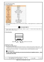
4-1. Colors and signals
Colors
Functions
Black
Output 1
White
Output 2
White(Blue)
Output 3
Orange
Trouble output
Gray
Output common minus
Red
Input common plus
Green
Input 1
Yellow
Input 2
Purple
Input 3
White(Yellow)
Input 4
Brown
+VIN
Blue
-VIN
Yellow(Red)
Serial input(RXD)
Yellow(Green)
Serial output(TXD)
Yellow(Black)
Serial GND
Colors in parenthesis indicate ink color of both sides line printing. Input/output direction is mentioned on the
basis of PBS.
ENFORCEMENT
* Connect unused input cable to input common +(Red) or open it. Connect unused output cable to
output common –(Gray) or open it.
4-2. Operating lamp
5. Detecting area setting
5-1. Detecting area setting software
Start application software and set detection area with mouse or numerical input, referring monitor of PC. It is
convenient to make a fine adjustment of detection area because of checking operating state with monitor of PC.
Each setting area can be saved in file. See instruction manual of software application in details.
ENFORCEMENT
Be sure to adjust, checking detecting area data and real time data with application software. Check
operating state after setting.
Title
Measuring Distance Type Obstacle Detection
Sensor PBS-03JT-V01 Instruction Manual
Drawing
No.
C-41-2430
11/19
Output 3
Output 2
Output 1
Power(Flickers when trouble)

