Document No: C-61-00003-3
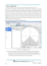
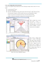
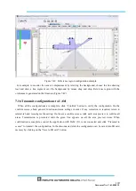
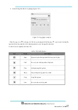
Figure 7-49
Reference region configuration example
For example, to monitor the sensor’s displacement by referring the background, choose the line drawing
tool and draw a line segment over the background by mouse drag and drop. Reference region with the
±tolerance is generated on that location (Figure 7-49).
7.16 Transmit configurations to UAM
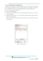
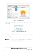
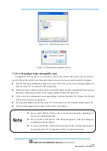
When all the configurations are complete, click “Confirm” button to verify the configuration. On the
confirm screen, check general, function and area settings in order. If any correction is required, return to
related tab and reconfigure the setting. On the area confirm screen, click each area preview to confirm all
areas. Transmission is prevented until the green line appears on all the area preview items. When
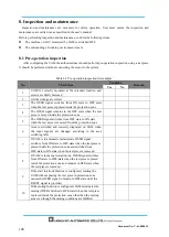
confirmation is complete, connect the application with UAM if it is not connected and click “Transmit to
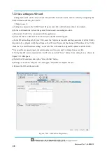
sensor” to transmit the configuration. In the disconnected state the configuration can be saved into SD card
memory by clicking on the “Save to SD card” button.
Summary of Contents for UAM-05LP
Page 1: ... Document No C 61 00003 3 ...
Page 104: ... Document No C 61 00003 3 Figure 7 33 b Function Figure7 33 c Area ...
Page 107: ... Document No C 61 00003 3 Figure 7 36 a Project report tab Figure 7 36 b Error report tab ...
Page 148: ... Document No C 61 00003 3 13 External dimension 13 1 UAM 05LP ...
Page 149: ... Document No C 61 00003 3 13 2 Base mounting bracket ...
Page 150: ... Document No C 61 00003 3 13 3 Rear mounting bracket ...
Page 151: ... Document No C 61 00003 3 13 4 Cover Protection Bracket ...
Page 152: ... Document No C 61 00003 3 14 EC Declaration of conformity ...
Page 153: ... Document No C 61 00003 3 ...

