Document No: C-61-00003-3
3.3 Operation principle
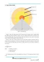
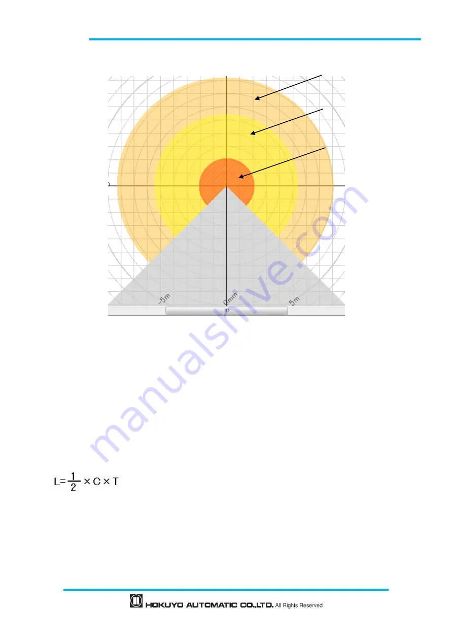
Figure 3-4 Scanning range
Figure 3-4 shows the scanning range of UAM. Protection zone and warning zones
are configured using
the UAM Project Designer application software. Any object or human beings entering the protection zone
will lead the OSSD signal to change from ON-state to OFF-state. Similarly, an object detected in the warning
zones will lead the warning signals to change to OFF-state.
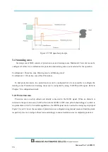
Distance to the object is measured using the Time of Flight (TOF) principle. Pulsed laser beams are
radiated into the scanning range of 270º by the rotating motor. These pulsed laser beams are reflected back
by objects inside the scanning range. The duration of reflected beams are used for distance calculation as
shown below:
Where, L
=
Distance of the object
C
=
Speed of the light
T
=
Time difference
The operating principle of TOF is schematically shown in Figure 3-5. The angular resolution of UAM is
0.125°.
Protection zone
Warning zone 1
Warning zone 2
Summary of Contents for UAM-05LP
Page 1: ... Document No C 61 00003 3 ...
Page 104: ... Document No C 61 00003 3 Figure 7 33 b Function Figure7 33 c Area ...
Page 107: ... Document No C 61 00003 3 Figure 7 36 a Project report tab Figure 7 36 b Error report tab ...
Page 148: ... Document No C 61 00003 3 13 External dimension 13 1 UAM 05LP ...
Page 149: ... Document No C 61 00003 3 13 2 Base mounting bracket ...
Page 150: ... Document No C 61 00003 3 13 3 Rear mounting bracket ...
Page 151: ... Document No C 61 00003 3 13 4 Cover Protection Bracket ...
Page 152: ... Document No C 61 00003 3 14 EC Declaration of conformity ...
Page 153: ... Document No C 61 00003 3 ...

