Document No: C-61-00003-3
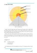
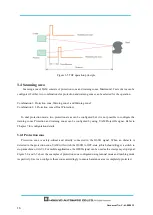
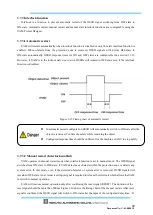
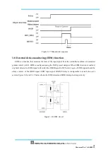
Figure 3-5 TOF operation principle
3.4 Scanning area
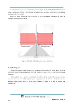
Scanning area of UAM consists of protection zone and warning zones. Maximum 32 sets of area can be
configured. Further, two combinations for protection and warning zones can be selected for the operation.
Combination 1: Protection zone, Warning zone 1 and Warning zone 2
Combination 2: 2
Protection zones (Dual Protection)
In dual protection mode, two protection areas can be configured but it is not possible to configure the
warning zones Protection and warning zones can be configured by using UAM Project Designer. Refer to
Chapter 7 for configuration details.
3.4.1 Protection zone
Protection zone is safety-critical and directly connected to the OSSD signal. When an obstacle is
detected in the protection zone, UAM will switch the OSSD to OFF-state
(which
should trigger a switch to
stop a machine or AGV). For mobile applications, the OSSD signal can be used as the emergency stop signal.
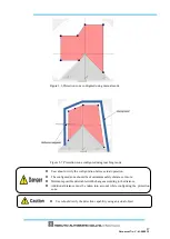
Figure 3-6 and 3-7 show the examples of protection zone configured using manual mode and teaching mode
respectively. User can configure these zones accordingly to ensure hazardous area is completely protected.
Summary of Contents for UAM-05LP
Page 1: ... Document No C 61 00003 3 ...
Page 104: ... Document No C 61 00003 3 Figure 7 33 b Function Figure7 33 c Area ...
Page 107: ... Document No C 61 00003 3 Figure 7 36 a Project report tab Figure 7 36 b Error report tab ...
Page 148: ... Document No C 61 00003 3 13 External dimension 13 1 UAM 05LP ...
Page 149: ... Document No C 61 00003 3 13 2 Base mounting bracket ...
Page 150: ... Document No C 61 00003 3 13 3 Rear mounting bracket ...
Page 151: ... Document No C 61 00003 3 13 4 Cover Protection Bracket ...
Page 152: ... Document No C 61 00003 3 14 EC Declaration of conformity ...
Page 153: ... Document No C 61 00003 3 ...

