Document No: C-61-00003-3
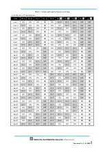
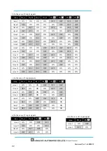
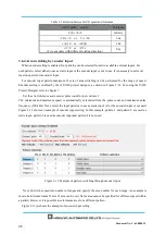
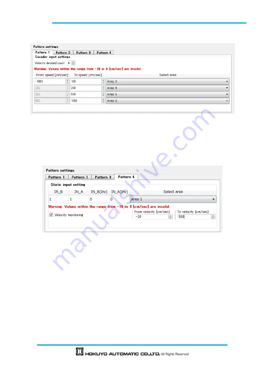
In this example, speed is divided into 4 ranges and each speed range is assigned Area 3 to Area 6.
Figure 3-13 (a) Example of encoder input setting
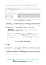
When the pattern is set for static input, area number and encoder speed monitoring are configured. Speed
monitoring monitors the speed of the encoder and if it exceeds the limit OSSD will be switched to OFF state.
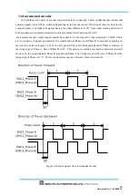
Figure 3-13(b) shows the example of static input setting. In this example, Area1 is assigned to the input
pattern and speed monitoring is enabled with the monitoring speed range -20 to 500cm/sec.
Figure 3-13 (b) Example of static input setting
3.7 OSSD
OSSD is safety-related signal. When humans or objects are detected in the protection zone, the OSSD
signal will switch to OFF state from ON-state.
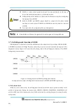
OSSD signal has the self- diagnostic function which tests the
signal periodically by switching it to OFF state for a brief period. Signal is continuously switched to
OFF-state when an error is detected during the diagnostic.
Output states of OSSD1 and OSSD2 signal are identical. Both signals should be connected to the safety
related machines or control system to fulfill the required safety level. If OSSD3 and OSSD4 are used they
must be connected in the same manner.
Summary of Contents for UAM-05LP
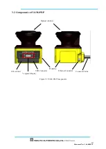
Page 1: ... Document No C 61 00003 3 ...
Page 104: ... Document No C 61 00003 3 Figure 7 33 b Function Figure7 33 c Area ...
Page 107: ... Document No C 61 00003 3 Figure 7 36 a Project report tab Figure 7 36 b Error report tab ...
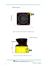
Page 148: ... Document No C 61 00003 3 13 External dimension 13 1 UAM 05LP ...
Page 149: ... Document No C 61 00003 3 13 2 Base mounting bracket ...
Page 150: ... Document No C 61 00003 3 13 3 Rear mounting bracket ...
Page 151: ... Document No C 61 00003 3 13 4 Cover Protection Bracket ...
Page 152: ... Document No C 61 00003 3 14 EC Declaration of conformity ...
Page 153: ... Document No C 61 00003 3 ...

