Document No: C-61-00003-3
3.7.3 Interlock function
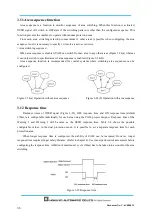
Interlock is a function to prevent automatic restart of the OSSD signal switching from OFF-state to
ON-state. Automatic restart, manual restart and manual start interlock functions are configurable using the
UAM Project Designer.
3.7.3.1 Automatic restart
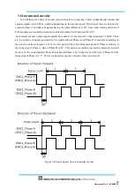
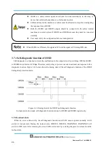
UAM will restart automatically when interlock function is disabled or only the start interlock function is
enabled. When obstacle from the protection zone is removed, OSSD signals switch from OFF-state to
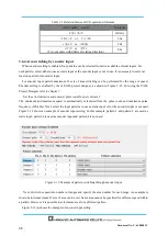
ON-state automatically. OSSD response times for ON and OFF states are configurable (See section 3.12).
However, if UAM is in the lockout state due to error,
OSSDs will remain in OFF-state even if the interlock
function is disabled.
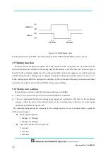
Figure 3-15 Timing chart of automatic restart
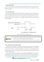
3.7.3.2 Manual restart (Interlock enabled)
UAM operates in manual restart mode when interlock function is set to manual mode. The OSSD signal
switches from ON-state to OFF-state, if UAM detects any obstacle within the protection zone or detects any
system error. In this mode, even if the detected obstacles or system error is removed, OSSD signals will
remain in OFF-state. An external reset input signal is required to release the interlock which allows the UAM
to
switch
to normal operation.
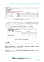
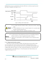
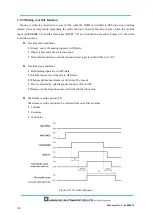
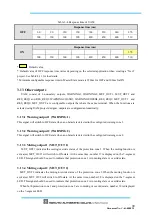
UAM will resume normal operation only after confirming the reset signal (RESET). The duration of the
reset signal should be more than 500ms. Figure 3-16 shows the timing chart of the manual restart. After reset
signal is confirmed, the OSSD signal will switch to ON-state after the lapse of the configured delay time. . If
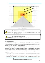
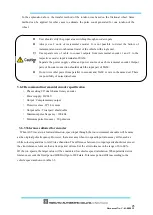
In automatic restart configuration OSSD will automatically switch to ON state after the
object is removed. Confirm the safety while removing the object.
Configured response time should be sufficient for the machine or AGV to stop safely.
Summary of Contents for UAM-05LP
Page 1: ... Document No C 61 00003 3 ...
Page 104: ... Document No C 61 00003 3 Figure 7 33 b Function Figure7 33 c Area ...
Page 107: ... Document No C 61 00003 3 Figure 7 36 a Project report tab Figure 7 36 b Error report tab ...
Page 148: ... Document No C 61 00003 3 13 External dimension 13 1 UAM 05LP ...
Page 149: ... Document No C 61 00003 3 13 2 Base mounting bracket ...
Page 150: ... Document No C 61 00003 3 13 3 Rear mounting bracket ...
Page 151: ... Document No C 61 00003 3 13 4 Cover Protection Bracket ...
Page 152: ... Document No C 61 00003 3 14 EC Declaration of conformity ...
Page 153: ... Document No C 61 00003 3 ...

