Document No: C-61-00003-3
6. Wiring
This chapter describes safety precaution when wiring the UAM.
6.1 Precautions
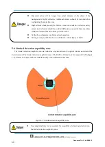
During electric wiring make sure that all devices are disconnected from power supply. Switch off all the
power supply during wiring. Confirm that power supply is OFF.
Do not exceed cable length stated in the specification of UAM.
6.2 Power supply
Make sure that power supply is within the range of DC 24V
±
10%. For battery operation, power supply
should be within the range of DC 24V -30% / +20%. UAM could be damaged if rated output voltage
exceeds this range.
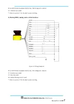
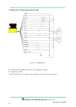
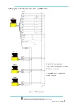
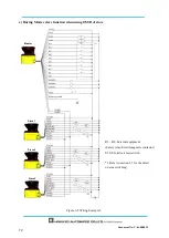
6.3 Wire color and function
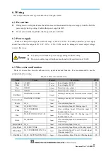
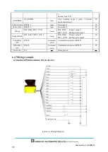
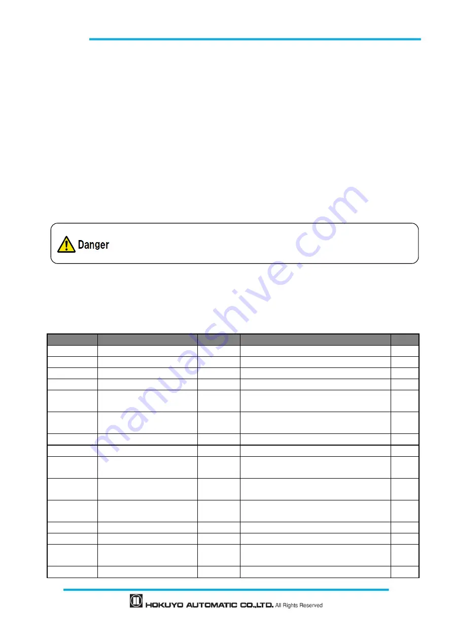
Table 6-1 shows the color of each lead wire, signal name and function. It is recommended to use the
shielded cable for wiring.
Table 6-1 Wire color and function
Color
Signal
Function
Description
AWG
Brown
+ 24 DC
Power
Power Supply
:
DC 24V
22
Blue
0V DC
Power
Power Supply
:
DC 0V
22
Red
OSSD1
Output
Protection zone output 1
26
Yellow
OSSD2
Output
Protection zone output 2
26
Red/Black
WARNING 1/ OSSD3
Output
Warning zone output 1/Protection zone output
3
28
Yellow/Black
WARNING 2/ OSSD4
Output
Warning zone output 2/Protection zone output
4
28
Purple
IN_A
Input
Area switching Input A
28
Gray
IN_B/ MUTING 3
Input
Area switching
Input B / Muting input 3
28
White
IN_C/OVERRIDE1/
ENC1_A
Input
Area switching Input C/Override input 1/
Encoder input 1_A
28
Pink
IN_D/ MUTING 1/ENC1_B
Input
Area switching Input
D
/
Muting input
1
/
Encoder input 1_B
28
Green
IN_E/EDM1
Input
Area switching Input E
/
External device
monitoring 1
28
Purple/Black
IN_A
Input
Area switching Input A invert
28
Gray/Black
IN_B/ MUTING4
Input
Area switching Input B invert
/
Muting input 4
28
White/Black
IN_C/OVERRIDE2/ENC2_A
Input
Area switching Input C invert
/
Override input
2/Encoder input 2 A
28
Pink/Black
IN_D/
MUTING2/ENC2_B
Input
Area switching Input D invert
/
Muting input
28
For safety, switch OFF the power supply during electrical wiring.
Do not use cables longer than those mentioned in the specification of UAM.
Summary of Contents for UAM-05LP
Page 1: ... Document No C 61 00003 3 ...
Page 104: ... Document No C 61 00003 3 Figure 7 33 b Function Figure7 33 c Area ...
Page 107: ... Document No C 61 00003 3 Figure 7 36 a Project report tab Figure 7 36 b Error report tab ...
Page 148: ... Document No C 61 00003 3 13 External dimension 13 1 UAM 05LP ...
Page 149: ... Document No C 61 00003 3 13 2 Base mounting bracket ...
Page 150: ... Document No C 61 00003 3 13 3 Rear mounting bracket ...
Page 151: ... Document No C 61 00003 3 13 4 Cover Protection Bracket ...
Page 152: ... Document No C 61 00003 3 14 EC Declaration of conformity ...
Page 153: ... Document No C 61 00003 3 ...

