
5
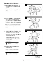
ASSEMBLY INSTRUCTIONS
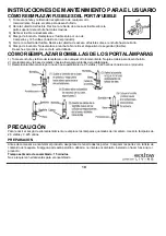
1. Take the antlers (E) and head and neck (A)
from inside the body (B). Place the parts flat
on the floor.
Insert the three metal rods at the top of each
leg (C) into the corresponding holes on the
body (B).
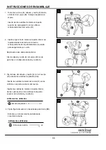
2. Insert the metal hook at the lower part of the
right front leg into the corresponding nut
on the left front leg to secure them in position.
Repeat this step for the left and right hind legs.
Attach the head and neck (A) to the body (B)
using the hooks at the base of the head and
neck (A).
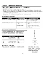
3. Fasten the base of the head and neck (A) to
the body (B) using the plastic ties (AA).
Insert the metal rod of the tail (D) into the hole
at the rear end of the body.
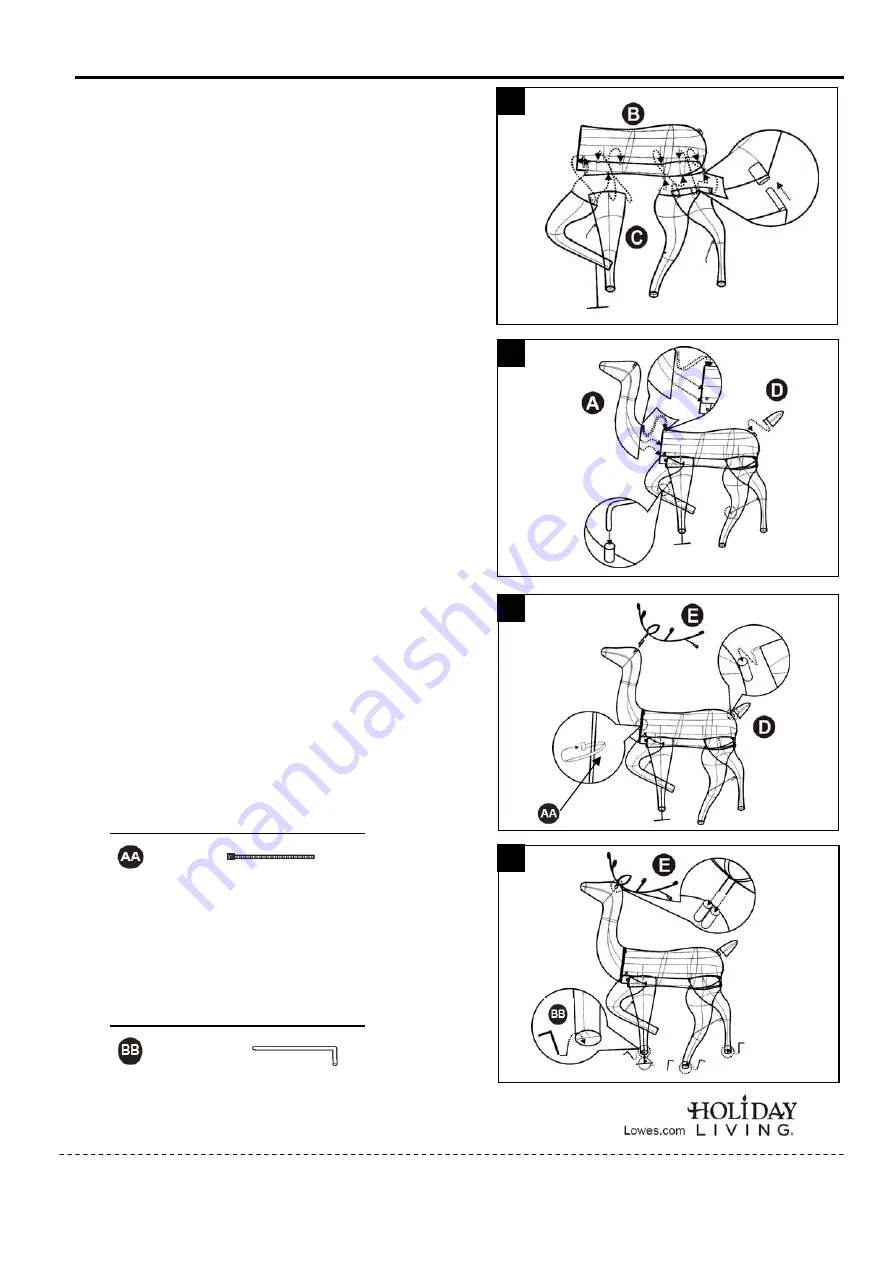
Insert the metal rods at the bottom of the
antlers (E) into the holes on the top of the
head and neck (A).
4. Secure the figure to the ground using the
ground stakes (BB).
Plug into a properly grounded receptacle.
5
1
2
3
4
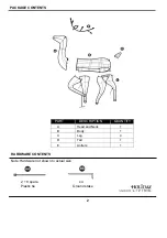
Hardware Used
Plastic tie x 2
Hardware Used
Ground Stake x4


