10
XL-LG20004UM-en-US Rev B · 2018-09-17 · Amendments and Errors Reserved · © SAF-HOLLAND, Inc., SAF-HOLLAND, HOLLAND, SAF,
and logos are trademarks of SAF-HOLLAND S.A., SAF-HOLLAND GmbH, and SAF-HOLLAND, Inc.
Installation Procedures
6. Installation Instructions
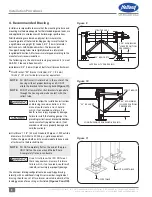
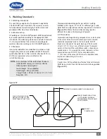
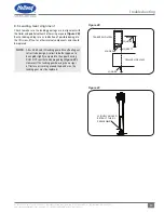
1. On a level surface, support the front of the trailer with
either a kingpin stand, or while coupled to a tractor
(Figure 13)
.
2. Set the parking brakes and chock the tires.
Failure to properly support the trailer and
chock the tires during installation of
landing gear could create a crush hazard
which, if not avoided, could result in
death or serious injury.
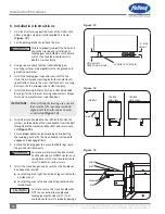
3. Using a square, check that the trailer landing gear
mounting surfaces are perpendicular to the ground and
parallel to each other.
4. Install the landing gear legs and cross-shaft to the
trailer frame. Torque mounting bolts to manufacturer’s
specifications. Ensure the cross shaft lock nuts are snug,
but cross-shaft is allowed side to side free-play.
5. Install the bracing. Refer to Section 4, (Recommended
Bracing), for the minimum bracing requirements. Torque
fasteners to manufacturer’s specifications.
IMPORTANT:
After installing the bracing, use a square
to ensure that the legs have remained
aligned with the trailer and each other
as illustrated
(Figure 14)
.
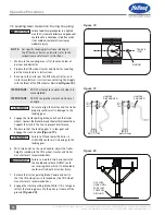
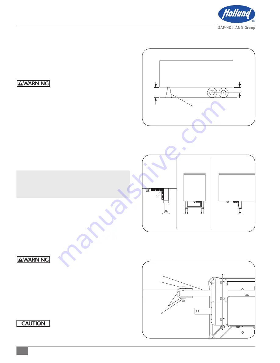
6. Install the crank handle onto the shift shaft. Position the
washers on the outside of the crank handle. Insert the bolt
through both the washers and the shaft, and secure with
nut
(Figure 15)
.
7. Ensure proper operation by extending and retracting
the landing gear. Verify the crank handle is allowed to
engage and disengage freely.
8. Extend the landing gear to ensure that both legs reach
the ground simultaneously.
Failure to maintain two hand control of
handle and release SLOWLY could cause
spring back which, if not avoided, could
result in death or serious injury.
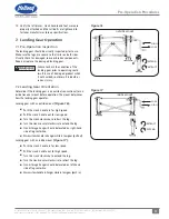
9. Install the crank hanger, and ensure that the handle can
be adequately secured.
Locate Hanger on right-hand side of leg centerline for
outside mount.
Locate Hanger on left-hand side of leg centerline for
inside mount.
Failure to secure the crank handle when
NOT in use could, allow unplanned
landing gear extension which, if not
avoided, could result in property damage.
Figure 13
Figure 14
CORRECT
SQUARE
TRAILER
END VIEW
TRAILER
SIDE VIEW
SUPPORT AT KINGPIN
“A” RIDE
HEIGHT
FIFTH WHEEL
OPERATING HEIGHT
Figure 15
WASHERS
BOLT
SHAFT
NUT

