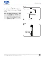
13
XL-LG20004UM-en-US Rev B · 2018-09-17 · Amendments and Errors Reserved · © SAF-HOLLAND, Inc., SAF-HOLLAND, HOLLAND, SAF,
and logos are trademarks of SAF-HOLLAND S.A., SAF-HOLLAND GmbH, and SAF-HOLLAND, Inc.
Operation Procedures
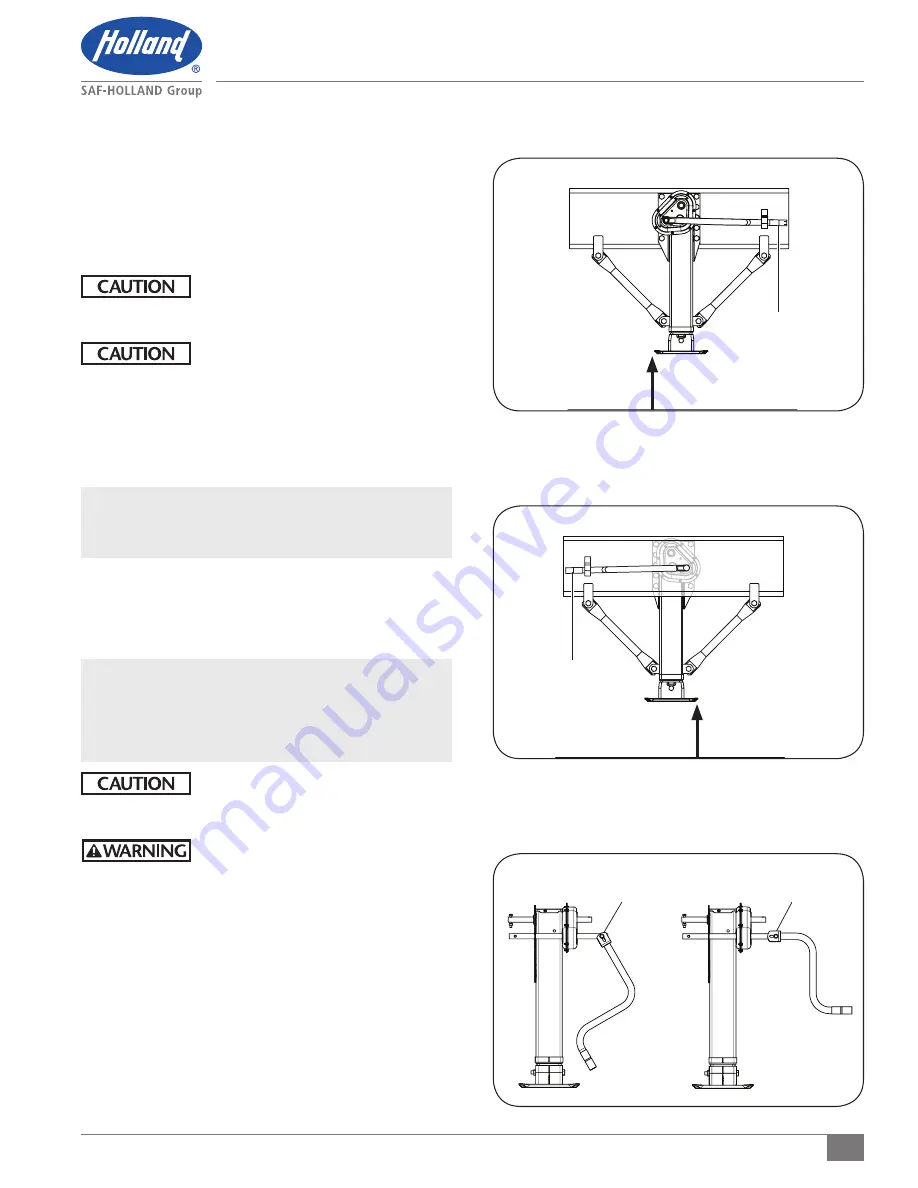
Figure 22
Figure 23
Figure 21
9. Release the tractor parking brake. Re-verify that the fifth
wheel jaws are locked per the fifth wheel manufacturer's
recommendations. Reapply the tractor parking brake.
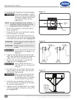
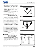
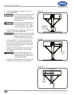
10. Shift the landing gear into high gear and fully retract.
Shift the landing gear into low gear and secure the crank
handle. For outside mount use
Figure 21
,for inside
mount use
Figure 22
.
Failure to retract the landing gear fully
before moving the trailer could result
in property damage.
Failure to secure the crank handle when
NOT in use could allow unplanned
landing gear extension which, if not
avoided, could result in property damage.
11. Complete all pre-trip inspection and operation procedures.
7.4 Landing Gear Operation During Uncoupling
NOTE:
For specific uncoupling instructions relating to
the fifth wheel, tractor, and trailer, refer to the
respective manufacturer's instructions.
1. Position the tractor and the trailer on a well lit, level
surface, clear of persons and obstacles. Verify that the
surface beneath the landing gear is capable of supporting
the trailer weight. Also ensure that the tractor and trailer
are in line with each other.
NOTE:
If necessary, place landing gear pads on a support
plank to prevent the landing gear from sinking
into the supportive surface. (This is especially
important with liquid cargo, where a shift in the
contents could overturn the trailer).
Failure to align the tractor and trailer
properly could result in damage to the
landing gear.
Failure to rest the landing gear pads on
a hard, flat surface, could result in trailer
tip-over which, if not avoided, could
result in death or serious injury.
2. Engage the trailer brakes. Slowly back tractor tightly against
the trailer. Set the tractor brakes, and chock the trailer wheels.
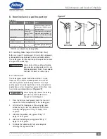
3. Engage the landing gear crank handle and shift to high
gear
(Figure 23)
.
SECURE
HANDLE
SECURE
HANDLE
OUTSIDE MOUNT
INSIDE MOUNT
HANDLE
ENGAGED
HANDLE
DISENGAGED

