background image


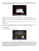
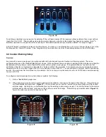
Figure 30 


Touch Screen Switches may be used as "enable/input" from software created I/O (for example nitrous enable) or from a user defined 

Inputs from the I/O ICF.  These switches may also be used to trigger an output once the desired Input has been created.  Note** A 

switched output used in conjunction with a sensor input **both switch and sensor input must be enabled** for output to trigger. 


A TSLCD “Switch” must first be created in the PC software.  To create, you must first define a +12v (H) or Ground (G) input.  Go to the 

Pin Map and the “View LCD” screen.  Then “drag and drop” the input onto one of the 10 available positions on the LCD Pin Map. 


9.4 Caution Warning/Setup 


Overview 


Any item with a numeric reading can be configured with both high side and low side Caution and Warning outputs.  These are 

configured using one of the “Needle/Data Gauge” screens.  Once configured there, a caution or warning will be indicated on a Dial (the 

background will turn yellow or red) or Digital (the number will turn yellow or red) gauge.  This system defines a “caution” as a first 

notification of trouble.  A “warning” is a value that is a “worse condition” than a caution.  For example, you may set up engine coolant 

temperature to have a “caution” trigger at 220°F, and a warning to occur at 240°F.  You can configure a “low side” caution and warning 

as well.  You would use this for oil pressure, for example.  You can set up a low side caution to occur at 25 PSI and a low side warning 

to occur at 15 PSI. 


To configure a caution/warning for a certain channel, perform the following: 


1)  Go to a “Needle/Data” gauge view. 


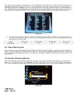
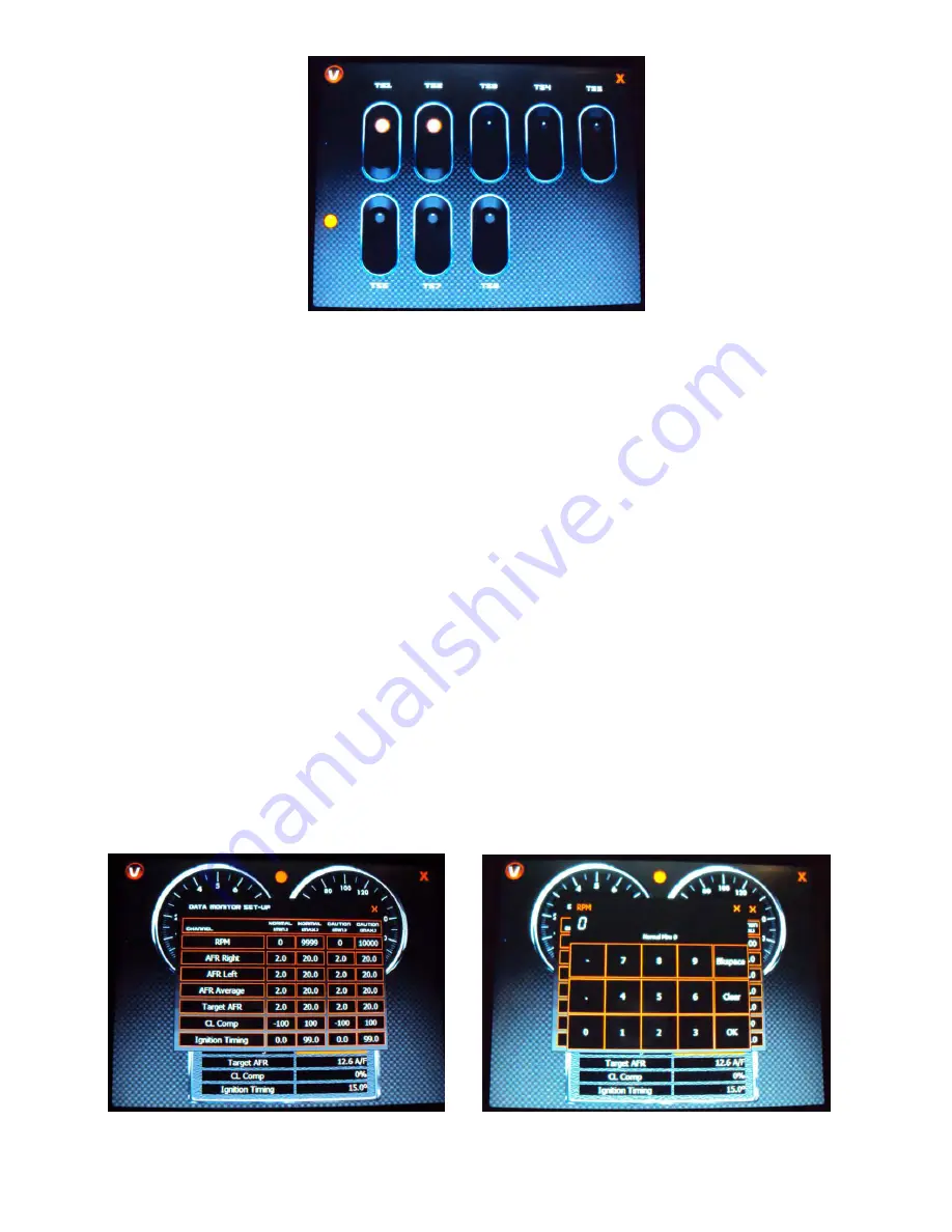
2)  If the channel you want to create a caution/warning for is available, click once on the name of that channel.  This will bring up 

the “Data Monitor Set-Up Screen” (

Figure 31

).  On this screen you can set the “normal” min and max range, and the caution 

min/max range.  By doing so, you automatically set up the warning min/max range as well.  To enter the values for the normal 

min/max and caution min/max, click once on the number you want to change.  This will bring up a number editor (

Figure 32

).  

Type in the value you want and click once on “OK”. 


                                        Figure 31                                                                 Figure 32 


Summary of Contents for EFI 553-103

Page 1: ...ave previously been enabled and pin mapped in the calibration Download internal ECU data logs to the SD memory card What the Touch Screen does not allow you to do in regards to tuning and setup Perfor...

Page 2: ...ring step after the wiring connections are completed Wiring connections are as follows Figure 2 White Wire Connect to SWITCHED 12v ignition power This power should only be active when the ignition swi...

Page 3: ...I programs loaded on the touch screen are HEFI Config Tuning application for all tuning parameters HEFI Flasher Allows for ECU firmware flashing updating once version 330 or higher has been installed...

Page 4: ...are covered in the lengthy instructions included in the PC software ECU and system wiring Initial system configuration and setup Detailed EFI tuning there is a help screen available on every screen i...

Page 5: ...the update rate of the monitor may be very slow Figure 6 TPS Autoset If a TPS Autoset has not been performed you will see a TPS Autoset message button on the right side of the screen Before the engine...

Page 6: ...ft This will take you to the main selection screen consisting of Configuration Tuning Tools and Datalog functions To exit the program you must select Tools and Exit Program 6 1 Configuration The Confi...

Page 7: ...most left area If you want to see other areas there are two options 1 Use the Move Left Right Up Down buttons at the top right of the screen to move one row or column at a time 2 Use the Move button a...

Page 8: ...his will bring up a calculator Figure 17 You can type in a single number for all the cells 14 for example or perform a math offset divide by multiply addition subtraction There is also a fill column a...

Page 9: ...sted Static Timing Allows for a fixed timing to be entered and removed This is used when syncing the timing By fixing the timing to a single value it is much easier to check for synchronized timing al...

Page 10: ...files in the internal ECU data logger Figure 24 They can then be downloaded one at a time Select one file and then click the Download button Delete will select a single file and Delete All will delet...

Page 11: ...on for all the gauges is provided They can be changes as desired To change the view click on the V in the upper right of the screen and a View Selection Screen will appear Figure 25 Figure 25 9 3 View...

Page 12: ...a limited amount of channels that can be configured Figure 28 4 Bar Tachometer Large tachometer readout display Figure 29 5 Switch Panel The switch panel can be used to replace physical input switches...

Page 13: ...igital the number will turn yellow or red gauge This system defines a caution as a first notification of trouble A warning is a value that is a worse condition than a caution For example you may set u...

Page 14: ...35 39 PSI and 51 55 PSI and warnings below 35 and above 55 PSI you d set as follows Channel Normal min Normal Max Caution Min Caution Max Fuel Pressure 40 50 35 55 9 5 Caution Warning Light Every scre...

Reviews: