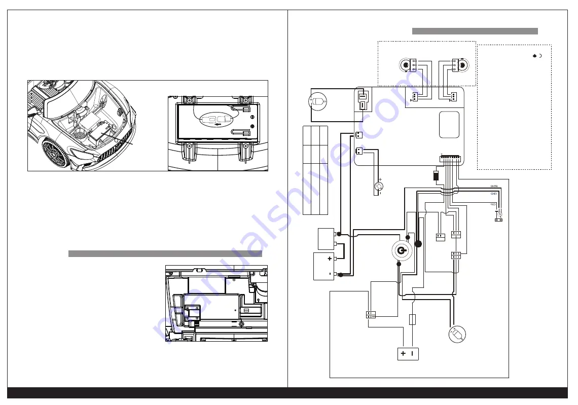
9.Battery connection
Loose two screws on the bonnet, remove the bonnet, connect two
red clip locks of two wires. Removable battery is optional, it can be
taken out for charging. (Release the lock, pull outward to take the
battery out.)
WARINING:
This product is not a vehicle for transportation, it should be used under
adult guidance. Parents should ensure that children have taken the
safety measures before using.
When change the gears, the accelerator should be release and the car
has completely come to a stop. Prohibit to change the gear while the car
is still moving, that can damage the wire and other transmission parts.
CIRCUIT DIAGRAM
This car has the auto-reset fuse, if the car
stops suddenly during driving, it is mainly
caused by instantaneous current exceeds
,and make the fuse to trip. Then just stop
operating for about 8 seconds, and this
fuse can be reset. Then turn on the power
switch again.
In order to avoid the fuse tripping and cut
off power supply, please pay attention to
the following matters:
This product can't overload, the maximum
load is 30kgs.
Don't drag anything behind products.
Don't let the water or other liquid into the batteries and other electrical
components.
Do not change the circuit system and the structure of the product.
7
6
unmovable
battery
FUSE
battery box
battery connection method
CN4
CN5
BG
VBA
T
CN3
CN10
CN1
+
V LS R HS CH BG G SW
pink
brown
M
M
CN6
White
Steering Wheel
Steering Motor
Red
CN7
Maximum current of LED lights,
MP3, MP4 power supply can’t
exceed 1A.
M
red 0.75
red 0.3
red
pedal
high / low speed
rocking switch
lights switch
Clutch switch
forward / backward
pink
glass tube fuse
1N5408
gray0.2
gray0.2
brown0.3
orange0.5
orange0.3
brown
purple 0.2
Wire uncrossed
Wire crossed
Motor wire connection terminals: 1) red point is
positive pole 2) gap is a negative pole
Motor connect wire :
A.550 Motor (
optional)
(1) Motor transfer wire is used 1.5 square wire
(2) Motor wire is used 1.0 squares wire
B.390 Motor (
optional)
(1) Motor transfer wire is used 1.0 square wire
(2) Motor wire is used 0.75 squares wire
BROWN
- NEGA
TIVE POLE
+ POSITIVE POLE
DC12V
BA
TTER
Y
RESETT
ABLE
FUSE
WHITE 0.2
YELLOW 0.5
YELLOW
BLUE 0.5
RED 0.2
BLACK 0.2
BLACK 0.2
BLACK 0.2
BLACK 0.2
BLACK 0.3
BLACK 0.2
BLACK
BLACK 0.75
BLACK
GREEN 0.2
GREEN 0.2
YELLOW 0.2
YELLOW 0.2
WHITE 0.2
BLUE 0.2
BLUE 0.75
BLUE 0.2
steering motor
potentiometer
electronic steering
wheel potentiometer
Special for
steering wheel
charging port
normally closed contact
steering motor
orange0.5
blue wire welding to the gap
(
-
)
yellow welding to red port
(
+
)
left driving motor
swing motor
driving motor
position
left motor
Right motor
Connector
Method for side wire welding of motor
black wire welding to red point,
yellow wire welding to the gap
Yellow wire welding to red point, black wire welding to the gap
big one
small head
Wire connection is as following:
Internal Circuit Diagram
(
Remote control first
)
550 gearbox


